Download
1 / 33
330 likes | 358 Vues
Learn about Instruction Set Architecture (ISA) focusing on memory models, registers, data types, and instructions for hardware and software interfaces. Explore the key components that define an ISA.

E N D
COMP2121: Microprocessors and Interfacing Instruction Set Architecture (ISA) http://www.cse.unsw.edu.au/~cs2121 Lecturer: Hui Wu Session 2, 2017
Contents • Memory models • Registers • Data types • Instructions
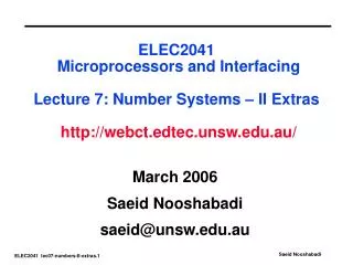
FORTRAN 90 C program program FORTRAN 90 C program program compiled compiled to ISA program to ISA program Software ISA level Hardware ISA program executed by hardware Hardware Instruction Set Architecture (ISA) • ISA is the interface between hardware and software • For (machine language) programmers (and compiler writers) • Don’t need to know (much) about microarchitecture • Just write or generate instructions that match the ISA • For hardware (microarchitecture) designers • Don’t need to know about the high level software • Just build a microarchitecture that implements the ISA
What makes an ISA? • Memory models • Registers • Data types • Instructions
What makes an ISA?#1: Memory Models • Memory model: how does memory look to CPU? • Issues • Addressable cell size • Alignment • Address spaces • Endianness
Addressable Cell Size • Memory has cells, each of which has an address • Most common cell size is 8 bits (1 byte) • AVR data memory has 8 bit cells • But not always! • AVR program memory has 16 bit cells (2 bytes) • Note – the data bus may be wider • i.e. retrieve several cells (addresses) at once
Alignment (1/2) • Many architectures require natural alignment, e.g. • 4-byte words starting at addresses 0,4,8, … • 8-byte words starting at addresses 0, 8, 16, …
Alignment (2/2) • Alignment often required because it is more efficient • Example – Pentium II • Fetches 8 bytes at a time from memory (8-byte wide data bus) • Addresses have 36 bits, but address bus only has 33 bits • But, alignment is NOT required (for backwards compatibility reasons) • 4-byte word stored at address 6 is OK • Must read bytes 0 to 7 (one read) and bytes 8 to 15 (second read) then extract the 4 required bytes from the 16 bytes read
Address Spaces • Princeton architecture or Von Neumann architecture (most used). • A single linear address space for both instructions and data • e.g. 232 bytes numbered from 0 to 232 -1 • (may not be bytes – depends on addressable cell size) • Harvard architecture • Separate address spaces for instructions and data • AVR AT90S8515 • Data address space: up to 216 bytes • Instruction address space: 212 16-bit words
AVR Address Spaces (1/3) • AVR microcontrollers have three address spaces • Program memory • Stores instructions and constants • Data memory • Stores data (variables) • Data EEPROM memory • Stores system parameters
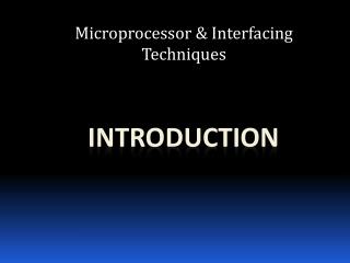
AVR Address Spaces (1/2) Data Memory Program Memory 0x0000 32 general purpose registers 0x0000 16 Bits 0x1F Program flash memory (1K bytes~128K bytes) 0x20 64 input/output registers 0x5F 0x60 Internal SRAM (128~4K bytes) External SRAM End Address 8 bits End Address
AVR Address Spaces (2/2) Data EEPROM Memory 0x0000 8 bits EEPROM memory (64~4K bytes) End address
Endianness • Different machines may support different byte orderings • Two orderings: • Little endian – little end (least significant byte) stored first (at lowest address) • Intel microprocessors (Pentium etc) • AVR microcontrollers for program memory • Big endian – big end stored first • SPARC, Motorola microprocessors • Most CPUs produced since 1992 are “bi-endian” (support both) • some switchable at boot time • others at run time (i.e. can change dynamically)
What makes an ISA?#2: Registers (1/2) • Two types • General purpose • Used for temporary results etc • Special purpose, e.g. • Program Counter (PC) • Stack pointer (SP) • Input/Output Registers • Status Register
Registers (2/2) • Some other registers are part of the microarchitecture NOT the ISA • Instruction Register (IR) • Memory Address Register (MAR) • Memory Data Register (MDR) • i.e. programmer doesn’t need to know about these (and can’t directly change or use them)
AVR Registers • General purpose registers are quite regular • Exception: a few instructions work on only the upper half (registers 16-31) • Bit limitations in some instructions (e.g. only 4 bits to specify which register) • There are many I/O registers • Not to be confused with general purpose registers • Some instructions work with these, others with general purpose registers – don’t confuse them • When X is needed as an index register, R26 and R27 are not available as general registers. • In AVR devices without SRAM, the registers are also the only memory – can be tricky to manage
General-Purpose Registers in AVR (1/2) • 32 general-purpose registers • named r0, r1, …, r31 in AVR assembly language • Broken into two parts: with 16 registers each, r0 to r15 and r16 to r31. • Each register is also assigned a memory address in SRAM space. • Register r0 and r26 through r31 have additional functions. • r0 is used in the instruction LPM (load program memory) • Registers x (r27 : r26), y (r29 : r28) and z (r31 : r30) are used as pointer registers • Most instructions that operate on the registers have direct, single cycle access to all general registers. Some instructions such as sbci, subi, cpi, andi, ori and ldi operates only on a subset of registers.
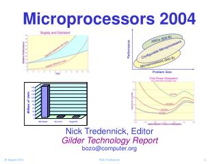
General-Purpose Registers in AVR (2/2) Address 0x00 r0 0x01 r1 0x1A r26 x register low byte 0x1B r27 x register high byte 0x1C r28 y register low byte 0x1D r29 y register high byte 0x1E r30 z register low byte 0x1F r31 z register high byte
Status Register in AVR (1/7) • The Status Register (SREG) contains information about the result of the most recently executed arithmetic/logic instruction. This information can be used for altering program flow in order to perform conditional operations. • SREG is updated after all ALU operations. • SREG is not automatically stored when entering an interrupt routine and restored when returning from an interrupt. This must be handled by software.
Status Register in AVR (2/7) Bit 7 6 5 4 3 2 1 0 • Bit 7 – I: Global Interrupt Enable • Used to enable and disable interrupts. 1: enabled. 0: disabled. • The I-bit is cleared by hardware after an interrupt has occurred, and is set by the RETI instruction to enable subsequent interrupts.
Status Register in AVR (3/7) Bit 7 6 5 4 3 2 1 0 • Bit 6 – T: Bit Copy Storage • The Bit Copy instructions BLD (Bit LoaD) and BST (Bit STore) use the T-bit as source or destination for the operated bit. A bit from a register in the Register File can be copied into T by the BST instruction, and a bit in T can be copied into a bit in a register in the Register File by the BLD instruction.
Status Register in AVR (4/7) Bit 7 6 5 4 3 2 1 0 • Bit 5 – H: Half Carry Flag • The Half Carry Flag H indicates a Half Carry (carry from bit 4) in some arithmetic operations. • Half Carry is useful in BCD arithmetic.
Status Register in AVR (5/7) Bit 7 6 5 4 3 2 1 0 • Bit 4 – S: Sign Bit • Exclusive OR between the Negative Flag N and the Two’s Complement Overflow Flag V ( S = N V). • Bit 3 – V: Two’s Complement Overflow Flag • The Two’s Complement Overflow Flag V supports two’s complement arithmetic.
Status Register in AVR (6/7) Bit 7 6 5 4 3 2 1 0 • Bit 2 – N: Negative Flag • N is the most significant bit of the result. • Bit 1 – Z: Zero Flag • Z indicates a zero result in an arithmetic or logic operation. 1: zero. 0: Non-zero.
Status Register in AVR (7/7) Bit 7 6 5 4 3 2 1 0 • Bit 0 – C: Carry Flag • Its meaning depends on the operation. For addition X+Y, it is the carry from the most significant bit. In other words, C= Rd7 • Rr7 +Rr7 • NOT(R7) + NOT(R7) • Rd7, where Rd7 is the bit 7 of x, Rr7 is the bit 7 of y, R7 is the bit 7 of x+y, • is the logical AND operation, and + is the logical OR operation. For subtraction x-y, where x and y are unsigned integers, it indicates if x<y. If x<y, then C=1; otherwise, C=0. In other words, C = NOT(Rd7)• Rr7+ Rr7 • R7 +R7 • NOT(Rd7).
What makes an ISA?#3: Data Types (1/3) • Numeric • Integers of different lengths (8, 16, 32, 64 bits) • Possibly signed or unsigned • Floating point numbers, e.g. 32 bits (single precision) or 64 bits (double precision) • Some machines support BCD (binary coded decimal) numbers • Non-numeric • Boolean (0 means false, 1 means true) – stored in a whole byte or word • Bit-map (collection of booleans, e.g. 8 in a byte) • Characters • Pointers (memory addresses)
Data types (2/3) • Different machines support different data types in hardware • e.g. Pentium II: • e.g. Atmel AVR:
Data types (3/3) • Other data types can be supported in software • e.g. 16-bit integer operations can be built out of 8-bit operations • Floating point operations can be built out of logical and integer arithmetic operations
What makes an ISA? #4: Instructions • This is the main feature of an ISA • Instructions include • Load/Store – move data from/to memory • Move – move data between registers • Arithmetic – addition, subtraction • Logical – Boolean operations • Branching – for deciding which instruction to perform next • I/O instructions – for controlling I/O devices
Summary: What makes an ISA? • Memory models • Registers • Data types • Instructions • If you know all these details, you can • Write machine code that runs on the CPU • Build the CPU
CISC vs. RISC (1/2) • How complex should the instruction set be? Should you do everything in hardware? • 2 “styles” of ISA design • CISC = Complex Instruction Set Computer • Lots of complex instructions – many of which take many clock cycles to execute • Examples: 8086 to 80386 • Classic example: VAX had a single instruction to evaluate a polynomial equation • RISC = Reduced Instruction Set Computer • Fewer, simpler instructions which can execute quickly (often one clock cycle) • Lots of registers • More complex operations built out of simpler instructions • Examples: SPARC, MIPS, PowerPC
CISC vs. RISC (2/2)) • Originally (80s) • CISC – 200+ instructions • RISC – ~50 instructions • Today • Number of instructions irrelevant • Many “CISC” processors use RISC techniques • e.g. 80486 … Pentium IV • Better to look at use of registers/memory • CISC – often few registers, many instructions can access memory • RISC – many registers, only load/store instructions access memory • Atmel AVR is a RISC microcontroller
Reading Material • Chapter 2, Microcontrollers and Microcomputers by Fredrick M. Cady.