Download
1 / 28
280 likes | 416 Vues
Linear Collider Flavour Identification.

E N D
Linear Collider Flavour Identification P Allport3, D Bailey1, C Buttar2, D Cussans1, C J S Damerell3, J Fopma4, B Foster4, S Galagedera5, A R Gillman5, J Goldstein5, T J Greenshaw3, R Halsall5, B Hawes4, K Hayrapetyan3, H Heath1, S Hillert4, D Jackson4,5, E L Johnson5, N Kundu4, A J Lintern5, P Murray5, A Nichols5, A Nomerotski4, V O’Shea2, C Parkes2, C Perry4, K D Stefanov5, S L Thomas5, R Turchetta5, M Tyndel5, J Velthuis3, G Villani5, S Worm5, S Yang4 • Bristol University • Glasgow University • Liverpool University • Oxford University • Rutherford Appleton Laboratory May 26, 2005
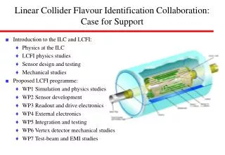
Linear Collider Flavour Identification: Activities • LCFI Outline • Simulation and Physics Studies • Sensor Development • Readout and Drive Electronics • External Electronics • Integration and Testing • Vertex Detector Mechanical Studies • Test-beam and EMI Studies LCFI is active in the development of the full vertex detector May 26, 2005
LCFI Physics Studies • Identification of b/c quarks • ZVTOP algorithm plus neural net • Modest improvement in b tagging over that achieved at SLD. • Improvement by factor 2 to 3 in charm tagging efficiency. • Charm tag interesting e.g. for Higgs BR measurements. • Identification of quark charge • Must assign all charged tracks to correct vertex. • Multiple scattering critical, lowest track momenta ~1 GeV. • Sum charges associated with b vertex: b quark charge identification Efficiency and purity of b and c jet tags May 26, 2005
Charge deposition, clustering, sparsification, track fitting Vertexing, track attachment, topological dependence Impact on physics quantities, individual physics channels Physics Studies: From MIPS to Physics The sensors studied are new devices; we need to model how they work. • We will need to develop understanding of: • Charge generation, propagation, and collection in new sensor types • Cluster finding, sparsification, fitting to tracks • Background effects and environment Provides feedback to sensor and electronics design dE/dx for 1 GeV p in 1 mm Si May 26, 2005
Charge deposition, clustering, sparsification, track fitting Vertexing, track attachment, topological dependence Impact on physics quantities, individual physics channels c decay vertex b decay vertex e+ primary vertex e- Physics Studies: From MIPS to Physics • Study factors affecting flavour identification and quark charge • Optimise flavour ID and extend quark charge determination to B0. • Examine effects of sensor failure. • Detector alignment procedures and effects of misalignments. • Polar angle dependence of flavour and charge identification. • Provides feedback to mechanical design; can shape overall detector design, e.g. additional layers, increased detector length vertex charge purity vs b-tag efficiency impact parameter resolution May 26, 2005
Charge deposition, clustering, sparsification, track fitting Vertexing, track attachment, topological dependence Impact on physics quantities, individual physics channels Physics Studies: From MIPS to Physics • With complete simulation, study physics processes for which vertex detector is crucial, for example: • Higgs branching fractions, requires flavour ID. • Higgs self-coupling, requires flavour and charge ID. • Charm and bottom asymmetries, requires flavour and charge ID. Plan to be prepared to react to discoveries at the LHC, and to show detector impact on physics. e+e- Zhh e+e- Zh May 26, 2005
337 ns 0.2 s Bunch Train x2820 0.95 ms Tracking and Timing Features at the Linear Collider What sort of tracking and vertexing is needed for the Linear Collider? • Vertex detectors for the Linear Collider will be precision devices • Need very thin, low mass detectors • No need for extreme radiation tolerance • Need high precision vertexing eg ~20 μm pixels • Can not simply recycle technologies used in LHC or elsewhere • High pixelization and readout implications • 109 pixels: must break long bunch trains into small bites (2820/20 = 141) • Read out detector many (ie 20) times during a train susceptible to pickup • …or store info for each bite and read out during long inter-train spaces Bunch Spacing May 26, 2005
Read out during the bunch train: Fast CCDs Development well underway Need to be fast (50 MHz) Proven track record at SLD Need to increase speed, size Miniaturise drive electronics Read out in the gaps: Storage sensors Store the hit information, readout between bunch trains (exploit beam structure) Readout speed requirements reduced (~1MHz) Can design to minimise sensitivity to electromagnetic interference Two sensor types under study; ISIS and FAPS Sensors for the ILC vertex detector ILC long bunch trains, ~109 pixels, relatively low occupancy May 26, 2005
Column Parallel CCD Readout time = N/Fout M N N “Classic CCD” Readout time NM/Fout Sensors: Column-Parallel CCDs • Fast Column-Parallel CCD’s (CPCCD) • CCD technology proven at SLD, but LC sensors must befaster, more rad-hard • Readout in parallel addresses speed concerns • CPCCD’s feature small pixels, can be thinned, large area, and are fast • CPC1: Two phase, 400 (V) 750 (H) pixels of size 20 20 μm2 Bump-Bonded CPCCD + Readout CPCCD1 (e2v) May 26, 2005
First-generation tests (CPC1): Noise ~100 e- (60 e- after filter). Minimum clock potential ~1.9 V. Max clock frequency above 25 MHz (design 1 MHz). Limitation caused by clock skew Extremely successful! Next generation in production (CPC2): Busline free design (two-level metal) Tests stitching, and choice of epi layers for varying depletion depth Range of device sizes for test of clock propagation (up to 50 MHz) Large chips are nearly the right size Level 1 metal Polyimide Level 2 metal Φ2Φ1 CPC2 Wafer Column-Parallel CCDs: Recent Results CPC2-70 9.2 cm May 26, 2005
Can store charge for many crossings ISIS: In-situ storage image sensor Signal stored safely until bunch train passed Test device being built by e2v “Revolver” variant of ISIS Reduces number charge transfers Increases radiation hardness and flexibility No shortage of good ideas 20 μm 20 μm Storage Sensors: ISIS May 26, 2005
Storage Sensors: ISIS 4 5 Storage gate 3 6 Storage gate 2 RSEL OD RD RG 1 7 8 OS Output node to column load Output gate Transfer gate 8 Photogate 20 19 Charge generation Storage Transfer 18 17 Readback from gate 6 May 26, 2005
FAPS architecture Flexible active pixel sensors Adds pixel storage to MAPS Present design “proof of principle” test structure Pixels 20x20 mm2, 3 metal layers, 10 storage cells MAPS FAPS Storage Sensors: FAPS • Results with initial design: • 106Ru b source tests: Signal to noise ratio between 14 and 17. • MAPS shown to tolerate high radiation doses. May 26, 2005
Storage Sensors: FAPS plans • Next step: Parametric test sensor • 64x64 identical pixels (at least) • Variants of write and read amplifiers and in storage cells • Will evaluate pixels in terms of • Noise • Signal • Radiation hardness • Readout speed • Optimisation is between • size of the pixel • readout speed • maximum amount of time available for readout • charge leakage Read/Write variations Memory cell variations May 26, 2005
Readout Electronics: CPR2 Readout Chip • Designed to match the Column Parallel CCD (CPC1 or CPC2) • 20µm pitch, maximum rate of 50MHz • 5-bit ADC, on-chip cluster finding • Charge and voltage inputs • New features for the CPR2 include • Cluster Finding logic, Sparse read-out • Better uniformity and linearity • Reduced sensitivity to clock timing • Variety of test modes possible • 9.5 mm x 6 mm die size, IBM 0.25µm • Recently delivered, testing beginning Major piece needed for a full module May 26, 2005
Vertex Detector Mechanical Studies • Thin Ladder (module) construction Goals are ambitious; • 0.1 % X/X0 Thinned silicon sensor, ultra-light support • Wire or Bump bondable, robust under thermal cycling • Materials and mechanical support technology under study • Carbon fibre, carbon foam, Silicon carbide foam, diamond, beryllium, etc. • Reticulated vitreous carbon (RVC) foam; 3% relative density, 3.1 mm = 0.05% X0 • Several interesting new materials available materials studies support technologies metrology May 26, 2005
Mechanical Studies: Support Structures • Thin Ladder Mechanical Considerations • Stresses introduced in processing imply “unsupported” Si > 50mm. • “Stretching” maintained longitudinal stability, but insufficient lateral support. • Re-visit using thin corrugated carbon fibre to provide lateral support. • Measurement and Stress Analysis • Supporting CCD on thin substrate studied at low temperatures. • Simulation (FEA) provides good guide. • Under study: sandwiched structure with foams. FEA analysis measurement May 26, 2005
Vertex Detector Global and Thermal Studies • Mounting schemes, layout, services, cooling etc • Must all be shown to be compatible with candidate technology • Large dependence on decisions in other work (e.g. sensors, electronics) • Thermal test stand under construction • Many mechanical challenges ahead • How to hold the ladders • Full detector layout • Thermal studies • How to cool the ladders • Stress analysis for candidate ladder support Many interesting mechanical challenges May 26, 2005
Testbeams and Electromagnetic Interference LCFI is actively developing test-beam capability with an aim to: • Understand the impact of the environment at the ILC on our sensors. • Beam induced RF had a serious impact on the SLD vertex detector. • The MDI panel of the world-wide study has identified EMI as one of the key issues to be addressed. • Collaborating with SLAC, US, and Japanese groups • Test full-sized prototype detector modules in a test-beam, including the study of: • Single hit efficiency • Influence of high magnetic fields • Resolution • Readout speed • Sparsification algorithms • Noise susceptibility May 26, 2005
The LCFI collaboration has enjoyed 3 years of success in ILC vertex detector R&D The new programme of work moves us from Research into prototype detector Development Overall goal is to have a fully-functional and test-beam proven detector module, including sensors, readout, and mechanical support, ready in 2010. The challenge is to take bench-top devices and develop them into fully functioning modules Successful development will put us in a good position to help build the ILC vertex detector New proposal includes 5 institutions 58 people, plus several students 7 new RA posts Linear Collider Flavour Identification: Proposal and Goals May 26, 2005
Progress made in understanding physics accessible at the ILC via: Flavour identification. Determination of b, c charge. Column Parallel CCD development progressing: LCFI will soon have sensors of scale close to that required for the ILC. Beginning to address remaining challenge of low mass drive circuitry. Storage sensor studies initiated: looks extremely promising Mechanical studies have demonstrated: Unsupported Si will not result in lowest mass sensors. Emphasis shifted to new materials. Milestones met or surpassed in last three years. Linear Collider Flavour Identification: Summary May 26, 2005
backup slides… May 26, 2005
Bump-Bonding, Radiation Damage • Bump-bonding • Standard in semiconductor packaging… but not for small quantities, large devices, thinned devices… • Necessary for dense, low-inductance connections • Primarily overseen by RAL, but Glasgow and Liverpool groups have experience • Radiation Damage studies • For any new vendor we will need to characterise the production process for resistance to radiation • Test bulk and surface damage for each sensor type • Look for charge transfer inefficiency (CTI) in CPCCD, ISIS • Much individual testing needed (time consuming) • Comparison to simulation, feedback to sensor design May 26, 2005
Driver Design Issues for CPCCD • High Current • Problem supplying ~10A to driver IC (thick wires) • Solution may be capacitive storage (charged at low rate between bunch trains, discharged at high rate when CCD is clocked during bunch train) • Waveform shape and timing • The driver IC will provide a high degree of control over the waveform • Shape and timing of CCD clock could be fine tuned to match readout IC timing • Adjustable clock drive voltage (aim to minimise power, without degrading charge transfer efficiency) Driver circuit May 26, 2005
Reset transistor Source follower Row select transistor sense node (n+) reset gate row select to column load VDD storage pixel #1 storage pixel #20 output gate transfer gate photogate n+ buried channel (n) p+ well p+ shielding implant reflected charge Charge collection reflected charge substrate (p+) High resistivity epitaxial layer (p) Storage Sensors – ISIS • ISIS Sensor details: • CCD-like charge storage cells in CMOS technology • Processed on sensitive epi layer • p+ shielding implant forms reflective barrier (deep implant) • Dual oxide thickness possible (Jazz Semiconductor) • Overlapping poly gates not likely in CMOS, may not be needed • Basic structure shown below: May 26, 2005
Storage Sensors – ISIS • Standard CMOS process doesn’t allow overlapping polysilicon or two thicknesses of oxide. • Modify dopant profiles to produce deeper buried channel: single oxide • Charge transfer is efficient, despite non-overlapping gates Sensor properties and design under study, looks promising Charge transfer (ISE-TCAD simulation) May 26, 2005