Download
1 / 18
190 likes | 368 Vues
Upgrade of the VLBA C-Band Feed & Receiver Design Review. Presented by S durand Designed by Bob Hayward and: Sivasankaran Srikanth (Feed Design) Hollis Dinwiddie (Mechanical Design) Everett Callan (Master Receiver Builder) Gordon Coutts & Craig Hennies (OMT Testing)

E N D
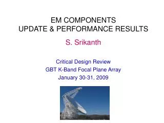
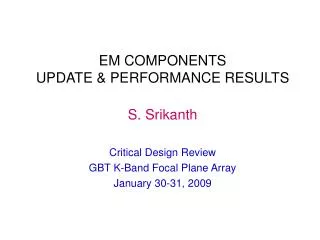
Upgrade of the VLBA C-Band Feed & ReceiverDesign Review Presented by S durand Designed by Bob Hayward and: SivasankaranSrikanth (Feed Design) Hollis Dinwiddie (Mechanical Design) Everett Callan (Master Receiver Builder) Gordon Coutts & Craig Hennies (OMT Testing) Marian Pospieszalski & the CDL Amplifier Group Pat Madigan & the VLA Machine Shop Michael Hedrick & the Green Bank Machine Shop 21 April 2011
Why Upgrade the VLBA C-band ? • Astronomers were eager to: • Access the Methanol Maser at 6,668 MHz GHz • Access to OH at 6016-6049 MHz • Carry out continuum observations with two IF’s separated by several GHz to allow the effects of the atmosphere to be subtracted out Example : IF-AC=4.0-4.5 and ID-BD=7.5-8.0 GHz • Limitations of the existing C-Band system: • Mediocre sensitivity due to old GAsFET LNA’s • Narrow bandwidth due to: • Septum Polarizer (4.5-5.2 GHz) • LNA’s (4.5-5.2 GHz) • Warm IF (4.5-5.2 GHz) • T105 Conversion (4.5-5.2 GHz)
T(Rx) for Old VLBA vs. New EVLA Rx’sAverage of 8 Dual-Channel Receivers
Required Specifications • To modify the VLBA Receiver to give us the RF performance that is as close to that achieved by an EVLA Receiver as possible.
Sri’s VLBA 4-8 GHz Feed Design • Profiled Corrugated Horn • Four machined sections • Ring-Loaded Mode Converter • Plugs into old feed location • Total Length = 37.5” • Outer Diameter = 18.5” • Weight = 55 lbs
Installation of the New Feed at VLBA Pie Town • Done with Feed S/N 01 • And Unmodified C-Band Rx • Uses a Transition Plate so an old Receiver can be attached to a new Feed and thus allow installation of lateral support brackets and turnbuckles. • Luckily feed is small enough to fit through the hatch (i.e., a crane is not required for hoisting it over the dish).
Existing VLBA C-Band Receiver Key: Ditom D3I4080-1 4-8 GHz Reactel 6B1-4850-700S12 4.5-5.2 GHz Miteq AMF-2B-4552 4.5-5.2 GHz Ditom D3I4080-1 4-8 GHz Cryo Pamtech CTB1107 Narda 4014C-30 GAsFET 4.5-5.2 GHz Keep PA -30 dB Toss LNA LNA New Omni-Spectra 2020-6616-06 TCal & PCal N/A RCP TCal & PCal TCal Pulse Cal PCal Omni-Spectra 2089-6203-00 -10 dB -6 dB Septum Pol Atlantic Microwave AMC 0935 Noise Diode Noise Diode High-Cal ( Not implemented on VLBA) LCP +20 Omni-Spectra 2020-6617-10 PA -30 dB T T T T Narda 4014C-30 GAsFET 4.5-5.2 GHz Pamtech CTB1107 Ditom D3I4080-1 4-8 GHz Reactel 6B1-4850-700S12 4.5-5.2 GHz Miteq AMF-2B-4552 4.5-5.2 GHz Ditom D3I4080-1 4-8 GHz The Cryogenic Pamtech Isolators were a surprise. There was no mention of them in the VLBA Technical Report #3. There must have been added after the 1st prototype Receiver was built.
Upgraded VLBA C-Band Receiver Key: Ditom D3I4080-1 4-8 GHz Ditom D3I4080-1 4-8 GHz TTE K5221-4/8G 4-8 GHz Ciao CA48-281 G=26dB Cryo Dorado 3ICC60-1 Narda 4014C-30 In HEMT 4-8 GHz Keep PA -30 dB Toss RCP 4-8 GHz Out LNA LNA New TCal & PCal N/A Noise/Com NC3205-G TCal & PCal RCP TCal Omni-Spectra 2089-6203-00 -10 dB Mactech CA7205U Hybrid OMT Omni-Spectra 2020-6617-10 Noise Diode 10 dB Pulse Cal LCP LCP 4-8 GHz Out PCal PA -30 dB T T T Narda 4014C-30 Dorado 3ICC60-1 InP HEMT 4-8 GHz Ditom D3I4080-1 4-8 GHz TTE K5221-4/8G 4-8 GHz Ditom D3I4080-1 4-8 GHz Ciao CA48-281 G=26dB Note that we leave out the High-Cal feature, which has never been used on the VLBA
Modifications & Problems • Making the modifications to the RF path of the receiver were relatively straight forward. • However, cooling the beast was a problem. • The old VLBA receiver had its Septum Polarizer tied to the 50°K Stage. • We wanted the new OMT to be tied to the 15°K Stage since it has more resistive losses. • Hollis spent quite a while fighting to minimize the final temperature that the 15°K Stage reached. • It was hard to get it much below 30°K and the temperature was very dependent on how many other receivers were on the same Helium line. • Required reducing the weight of the OMT as well as adding Space Blankets around the 50°K Radiation Shield. • It was also decided that the Thermal Gap assembly used in the EVLA design would need to be improved.
EVLA-StyleOMT &Thermal Gap AN72 Absorber wrapped around Thermal Gap to prevent Cavity Resonances. Includes: “Old” Thermal Gap + Heavy Blocks + Absorber Strip
VLBA-StyleOMT & Thermal Gap Includes: New Circular Thermal Gap with Choke Ring and long standoffs + “Swiss Cheese” Blocks to reduce thermal mass + Mount for Hybrid makes for an integrated Circular Polarizer
Recent Cool-down Results • Thanks to Hollis’ new Thermal Gap Assembly, the Model 22 is now cooling the RF Tree in the Prototype Receiver down to acceptable temperature levels. • The 15°K Cold Stage temperature is also less susceptible to variations from other fridges being connected to the Helium lines: • ~12-14°K when alone • ~14-16°K with one Model 350 on the loop • ~16-18°K with two Model 350 on the loop • The 2 x Model 350 scenario is what occurs on a VLBA Antenna. • VLBA C-Bands typically 15-25°K
Early RF Sensitivity Tests on VC#11Old EVLA vs. New VLBA Thermal Gap Using the new T-Gap assembly with its proper Choke Ring yields a vast improvement over that achieved on the EVLA with the old T-Gap design.
VLBA C-Band ReceiverOld vs. Interim vs. New Configuration RCP RCP IF Output A & C 500-1000 MHz Old T105 4.5-5.2 GHz Converter Module 4.5-5.2 GHz C 4.5-5.2 GHz Old C-Band Rx with Old T105 LCP LCP L104 #2 4.5-5.2 GHz RCP RCP Old T105 4.5-5.2 GHz Converter Module IF Output A & C 500-1000 MHz 4.0-8.0 GHz 4.5-5.2 GHz C 4.0-8.0 GHz LCP LCP Modified C-Band Rx with Old T105 (From old Rx) SMA L104 #2 RCP RCP IF Output A, B, C & D 500-1000 MHz 4.0-8.0 GHz C 4.0-8.0 GHz New T405 4 - 8 GHz Converter Module LCP LCP L104 #2 L104 #3 Modified C-Band Rx with New T405
Conclusions • Thanks to the new Thermal Gap design, the upgraded VLBA C-Band is now superior to the EVLA receiver. • Expect T(Rx) < 10°K from 4.2-8.0 GHz • It is now probably the most sensitive wideband system in the world at this frequency.