Download

1 / 24
240 likes | 306 Vues
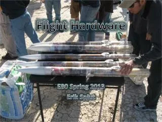
The Final Project Flight Hardware and all that Jazz. Prepared by Prof. Spjut Parroted by Prof. Duron. How excited will you be?. http://www.youtube.com/watch?v=7KksfV4Fi54. E80 Start to Finish.

E N D
The Final ProjectFlight Hardware and all that Jazz Prepared by Prof. Spjut Parroted by Prof. Duron
How excited will you be? • http://www.youtube.com/watch?v=7KksfV4Fi54
E80 Start to Finish • Your E80 experience up until now has been designed to create the necessary skills and understanding you will need to complete an engineering project. • The engineering project (i.e. rocket) is the context for helping you understand what it means to • be an engineer capable of delivering working products and deliverables that meet requirements and expectations.
What Will You Learn? • How to • Create an experimental plan with scientific and/or engineering objectives. • Design, prototype, test, and build an instrument package to achieve the objectives. • Fly the experiments, gather and analyze the data from each one. • Revise the experimental and flight plan for succeeding launches based on lessons learned from each flight.
Timeline • You will have 4 weeks to design, build, test and verify your avionics/instrumentation boards. • As engineers in training (a.k.a. Associate Technical Staff – ATS), you will need management approvals of your designs, and will need to ensure proper operation prior to launch day (or, before getting on the bus…).
Science/Engineering Goals (Wk1) • Obtain measurements/responses - temperature, pressure, humidity, trace gas concentration, particulate count, or wind speed, altitude, velocity, acceleration, rotation rate, internal temperatures, in-flight events (parachute ejection and landing), video. • You need to use at least two different types of sensors, and you can have a maximum of eight data channels. • Generate a complete parts list and complete schematics (e.g., power and bypass capacitors for op-amps) for your sensors and signal conditioning. • Each team has a budget of $50 for parts/sensors not in stock. • Your Section Professor and Professor Spjut must approvethe documentation of your plans.
Breadboard/Test (Wk2) • Fit allcomponents except for the battery, the data logger, and any power regulators, on a single breadboard. • Test your “data logging” on a USB DAQ and computer before you test it on the data logger to make sure the signals are in the 0-to-3.3V range. • Note: 5v is not 3.3v. • Make sure everything works. Demonstrate functionality to your section professor and Professor Spjut. • Demonstration must be achieved by the 3rd week (if parts are delayed, etc.).
Flight Hardware (Wk3) • Transfer everything onto your flight PC board and solder it into place. The top of the PC board is identical to your breadboard with two exceptions: The four outside power busses are slightly nearer the five-pin rows on the breadboard, and there is an extra power bus that runs up the center of the board, that you can use or not use. • There is a section in the middle of the PC board for a 7805 +5V voltage regulator, and up to three other voltage regulators. It also has space for one chip running horizontally instead of vertically. • The bottom of the board has mounting sockets for the data logger. Do not solder the data logger to the PC board. Simply put it in the sockets. The mounting holes on the PC board will accept either 4-40 or M3 screws. • All of your circuitry has to fit on one PC board, with the exception of remote sensors, which must have leads going to the PC board. • You must demonstrate that your system functions to your Section Professor and Professor Spjut.
Preparing to Fly (Wk4) • You want to be completely ready for pre-flight, flight, and data processing, and you want to have a complete run through of everything you will do in the field. It is much easier to debug and correct faulty procedures in the lab than in the high desert. • Check the flight characteristics of your finished rocket in Rocksim with the motors you will fly. • You also need to have a list of flight objectives for each flight and have it reviewed by your section professor or Professor Spjut.
Collecting Data • Measurements/responses will be digitized and stored onto a mirco-SD card using a Logomatic v2 Serial SD Datalogger.
Trade Offs • The Datalogger accepts analog signals (continuous), digitizes them (discrete), and stores them (for post-processing). • Digitizing records involves sampling, and the sampling capability of the logger depends on • Asciivs Digital data formats • Number of data channels acquired • You need to think about this…
Sampling Rates • Ascii mode • 1 channel - 1500 sps maximum • 2 channels - 750 sps maximum • 3 channels - 500 sps maximum • 4 channels - 375 sps maximum • 5 channels - 300 sps maximum • 6 channels - 250 sps maximum • 7 channels - 214 sps maximum • 8 channels - 187 sps maximum • Binary mode • 57% increase for 1 channel to 43% increase for 8 channels
Sampling Considerations • How many samples of a particular data record (measurement/response) do I need? • Data type matters • Slowly vs. Quickly varying • What you want to do with the data matters • Time vs. Frequency domain behavior • Can I actually take too few samples? (assuming that too many isn’t a problem…?)
Folding and Aliasing 0hz fnyquist 20 2fnyquist 3fnyquist 80 4fnyquist 120 …
How do I avoid Aliasing? • Two main approaches to avoid aliasing • Sample at a high enough rate • Limit the frequency content of your signals • Sampling at High Rates • How Hi is high enough? • Drawbacks of too much data? • Limit Frequency Content • How?
Filtering • Simply put… • If I have a signal and I remove the 100hz component, I am left with But, how can I do this ?
E21 Starts Here… • In practical terms, you need to identify a frequency range of interest (FRI). • In your case, you don’t yet have all the experience you need to do this, so work within the “capabilities” of your hardware. • Think about one good measurement, and what that would be. • How many good measurements can you get?
Antialising Filters • Think about introducing antialiasing filters into your design. • Even a 1st order filter can be useful • Remember to set the filter cutoff at no more than 80% of fnyquist.
Processing Your Data • You are likely to encounter • Offsets • Signal drift • Noisy data • Transient data • Random data • Clipped or saturated data • Data drop outs • Outliers
Stay Tuned… • Next lecture we will talk about time and frequency domain techniques for “processing” your data. • Not everything they tell you in E59 is true…