Download
1 / 25
250 likes | 279 Vues
Learn about arithmetic and logic circuits, including adders, subtractors, and ALU. Explore the beauty of 2’s complement representation and binary addition. Dive into full adder design, simplifying Boolean expressions, subtraction with 2’s complement, and condition codes for comparing numbers. Discover different adder architectures for faster performance.

E N D
Arithmetic and Logic Circuits Don Porter Lecture 12
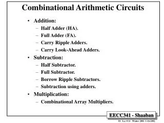
Topics • Arithmetic Circuits • adder • subtractor • Logic Circuits • Arithmetic & Logic Unit (ALU) • … putting it all together
Review: 2’s Complement N bits • 8-bit 2’s complement example: 11010110 = – 128 + 64 + 16 + 4 + 2 = – 42 • Beauty of 2’s complement representation: • same binary addition procedure will work for adding both signed and unsigned numbers • as long as the leftmost carry out is properly handled/ignored • Insert a “binary” point to represent fractions too: 1101.0110 = – 8 + 4 + 1 + 0.25 + 0.125 = – 2.625 -2N-1 2N-2 … … … 23 22 21 20 Range: – 2N-1 to 2N-1 – 1 “sign bit” “binary” point
A B CO CI S A B CO CI S A B CO CI S A B CO CI S A B CO CI S FA FA FA FA FA 4-bit adder Carries fromprevious column 1 1 0 1 Adding two N-bit numbers produces an (N+1)-bit result Binary Addition • Example of binary addition “by hand”: • Let’s design a circuit to do it! • Start by building a block that adds one column: • called a “full adder” (FA) • Then cascade them to add two numbers of any size… A: 1101B:+ 0101 10010 A3 B3 A2 B2 A1 B1 A0 B0 S4 S3 S2 S1 S0
A B CO CI S A B CO CI S A B CO CI S A B CO CI S FA FA FA FA Binary Addition • Extend to arbitrary # of bits • n bits: cascade n full adders • Called “Ripple-Carry Adder” • carries ripple through from right to left • longest chain of carries has length n • how long does it take to add the numbers 0 and 1? • how long does it take to add the numbers -1 and 1? An-1 Bn-1 A2 B2 A1 B1 A0 B0 Sn Sn-1 S2 S1 S0
Designing a Full Adder (1-bit adder) • Follow the step-by-step method • Start with a truth table: • Write down eqns for the “1” outputs: • Simplifying a bit (seems hard, but experienced designers are good at this art!)
Simplifying the Boolean for Adder • Start with definitions of xor (2 and 3 term): • Intuitively: Either only one is true, or all three are true • i.e., an odd number of 1’s • S is just the identify of a 3-term xor
Simplifying the Boolean for Adder • Definition of 2-term xor: • (Commutative) • (Distributive) • (Identity 7) • (Distributive) • (Def. of xor)
A B “Carry” Logic Ci Co “Sum” Logic S For Those Who Prefer Logic Diagrams • A little tricky, but only 5 gates/bit!
A B CO CI S A B CO CI S A B CO CI S A B CO CI S FA FA FA FA ~ = bit-wise complement B 0 B 1 B B B3 B2 B1 B0 Subtract But what about the “+1”? A3 A2 A1 A0 S4 S3 S0 S1 S0 Subtraction: A-B = A + (-B) • Subtract B from A = add 2’s complement of B to A • In 2’s complement: –B = ~B + 1 • Let’s build an arithmetic unit that does both add and sub • operation selected by control input:
Condition Codes • One often wants 4 other bits of information from an arith unit: • Z (zero): result is = 0 • big NOR gate • N (negative): result is < 0 • Sn-1 • C (carry): the most significant position produced a carry, e.g., “1 + (-1)” • Carry from leftmost column • V (overflow): indicates answer doesn’t fit • when: • both operands are +ve, but sum is -ve • both operands are -ve, but sum is +ve • another way to detect: • carry into leftmost column is different from carry out of leftmost column
Condition Codes To compare A and B, perform A–B and use condition codes: Signed comparison: EQ == Z NE != ~Z LT < NV LE <= Z+(NV) GE >= ~(NV) GT > ~(Z+(NV)) Unsigned comparison: EQ == Z NE != ~Z LTU < ~C LEU <= ~C+Z GEU >= C GTU > ~(~C+Z) • Subtraction is useful also for comparing numbers • To compare A and B: • First compute A – B • Then check the flags Z, N, C, V • Examples: • LTU (less than for unsigned numbers) • A < B is given by ~C • LT (less than for signed numbers) • A < B is given by NV • Others in table
A B CO CI S A B CO CI S A B CO CI S A B CO CI S A B CO CI S FA FA FA FA FA How long does addition take? (Latency) (TPD = max propagation delay or latency of the entire adder) An-1 Bn-1 An-2 Bn-2 A2 B2 A1 B1 A0 B0 C … Sn-1 Sn-2 S2 S1 S0 Worst-case path: carry propagation from LSB to MSB, e.g., when adding 11…111 to 00…001. Total latency (max delay in producing outputs) is proportional to N: TPD O(N) O(N) is read “order N” and tells us that the latency of our adder grows in proportion to the number of bits in the operands.
Can we add faster? • Yes, there are many sophisticated designs that are faster… • Carry-Lookahead Adders (CLA) • Carry-Skip Adders • Carry-Select Adders See textbook for details
A A B B Add Add/Sub S S Adder Summary • Adding is not only common, but it is also tends to be one of the most time-critical of operations • As a result, a wide range of adder architectures have been developed that allow a designer to tradeoff complexity (in terms of the number of gates) for performance. Smaller / Slower Bigger / Faster RippleCarry Carry Skip Carry Select Carry Lookahead At this point we’ll define a high-level functional unit for an adder, and specify the details of the implementation as necessary. sub
Shifting Logic • Shifting is useful for logic operations • applied to groups of bits • used for alignment • Shifting also used for “short cut” arithmetic operations • shift left logical (sll) • X << 1 is the same as 2*X (unless result overflows) • shift right logical (srl) • X >> 1 is the same as X/2 for unsigned numbers • shift right arithmetic (sra) • like a right shift, but maintains the sign bit • makes the sign bit “sticky” • X >>> 1 is the same as X/2 for 2’s-compl. numbers
Shifting Logic • Examples: • X = 2010 = 000101002 • Left Shift: shifts in a 0 from the right end • (X << 1) = 001010002 = 4010 • Right Shift: shifts in a 0 from the left end • (X >> 1) = 000010102 = 1010 • Signed or “Arithmetic” Right Shift: maintains the sign bit • -X = -2010 = 2’s complement of X = 111011002 • (-2010 >>> 1) = (111011002 >>> 1) = 111101102 = -1010
X7 X6 X5 X4 X3 X2 X1 X0 R7 R6 R5 R4 R3 R2 R1 R0 0 1 0 1 0 1 0 1 0 1 0 1 0 1 0 1 “0” SLL1 Shifting Logic: Other shift amounts • Circuit for shifting left by 1 • if SLL1 is true • shifts the input X: R X << 1 • if SLL1 is false • does not shift X: R X • Other shift amounts • shift left by 2 • rewire the multiplexors so each Xi feeds into Ri+2 • similarly: shift left by 4, etc. • also: srl and sra have similar circuitry • srl: each Xi feeds into a lower numbered Rj • sra: sign bit stays the same
Shifting Logic: Other shift amounts • Circuit for shifting left by any amount • make blocks for SLL1, SLL2, SLL4, SLL8, SLL16 • then, any arbitrary shift amount can be made by combining these shifts • example: SLL 13 = SLL (8 + 4 + 1) shift left by 16 shift left by 8 shift left by 4 shift left by 1 shift left by 2 SLL16 SLL8 SLL4 SLL2 SLL1 0 1 1 0 1 13 = 01101 in binary! shift amount
Boolean Operations • It will also be useful to perform logical operations on groups of bits. Which ones? • ANDing is useful for “masking” off groups of bits. • ex. 10101110 & 00001111 = 00001110 (mask selects last 4 bits) • ANDing is also useful for “clearing” groups of bits. • ex. 10101110 & 00001111 = 00001110 (0’s clear first 4 bits) • ORing is useful for “setting” groups of bits. • ex. 10101110 | 00001111 = 10101111 (1’s set last 4 bits) • XORing is useful for “complementing” groups of bits. • ex. 10101110 ^ 00001111 = 10100001 (1’s invert last 4 bits) • NORing is useful for.. uhm… • ex. 10101110 # 00001111 = 01010000 (0’s invert, 1’s clear)
Bi Ai This logic block is repeated for each bit (i.e. 32 times) 00 01 10 11 Bool Qi Boolean Unit • It is simple to build up a Boolean unit using primitive gates and a mux to select the function. • Since there is no interconnectionbetween bits, this unit can be simply replicated at each position. • The cost is about 7 gates per bit. One for each primitive function,and approx 3 for the 4-input mux. • This is a straightforward design • several optimizations possible to make it more efficient 2
A B Sub Boolean Bidirectional Shifter Add/Sub Bool Shft 1 0 Math 1 0 Result An ALU, at last (without comparisons) • Combine add/sub, shift and Boolean units • 2-bit Bool used for shifter flavor also • A is shift amount that B is shifted by 5-bit ALUFN Sub BoolShft Math OP 0 XX X 1 A+B 1 XX X 1 A-B X 00 1 0 B<<A X 10 1 0 B>>A X 11 1 0 B>>>A X 00 0 0 A & B X 01 0 0 A | B X 10 0 0 A ^ B X 11 0 0 A | B Flags N,V,C Z Flag
A B Sub Boolean Bidirectional Shifter Add/Sub Bool 1 0 Shft Math 1 0 Result A Complete ALU • With support for comparisons (LT and LTU) • LTU = ~C and LT = NV 5-bit ALUFN Sub Bool Shft Math OP 0 XX 0 1 A+B 1 XX 0 1 A-B 1 X0 1 1 A LT B 1 X1 1 1 A LTU B X 00 1 0 B<<A X 10 1 0 B>>A X 11 1 0 B>>>A X 00 0 0 A & B X 01 0 0 A | B X 10 0 0 A ^ B X 11 0 0 A | B <? 0 1 FlagsN,V,C Bool0 Z Flag
Next • Circuits for • Multiplication • Division • Floating-Point Operations