Download
1 / 27
290 likes | 386 Vues
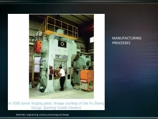
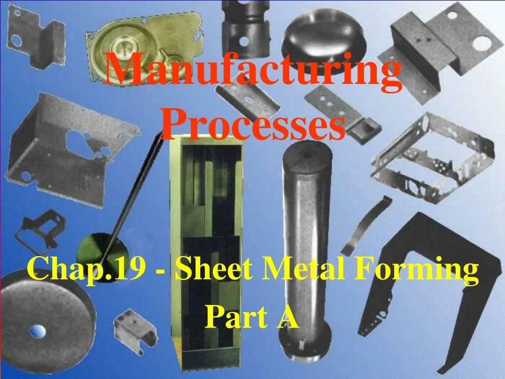
Manufacturing Processes. Chap.19 - Sheet Metal Forming Part A. Sheet Metal Forming. One of the oldest processes - more than 5000 years old. Can create light weight and versatile shapes. Carbon steel-most commonly used sheet metal. Low cost, good strength & formability. Sheet Metal Forming.

E N D
Manufacturing Processes Chap.19 - Sheet Metal Forming Part A
Sheet Metal Forming • One of the oldest processes - more than 5000 years old. • Can create light weight and versatile shapes. • Carbon steel-most commonly used sheet metal. • Low cost, good strength & formability.
Sheet Metal Forming • Superplastic forming • Peen forming • Explosive forming • Magnetic-pulse forming • Metal forming processes include: • Roll forming • Stretch forming • Drawing • Rubber forming • Spinning
Sheet Metal Forming • punching • blanking • embossing • bending • flanging • coining • lancing • piercing • perforating • parting • notching • Stamping operations include:
Shearing • Most basic operation. • Sheet is subjected to shear stresses as punch and die interact. (Fig. 16.2) • Components are punched hole and slug.
Shearing Mechanics • Edges of shear zone are not smooth. • Shearing starts with formation of cracks at top and bottom edges of workpiece. • Cracks eventually meet and separation of slug occurs. • Cracks generate the rough fracture surfaces. (fig. 16.5a left) • Rubbing of sheared edge and wall of punch & die create shiny burnished surfaces.
Shearing Mechanics • It is possible to obtain smooth edges via fine blanking. • Resulting Edges are highly square and smooth. • Sheet metal is placed between dies. (fig 16.5b) • Upper hold-down plate has a V-shaped stinger / protrusion. • Protrusion penetrates plate and creates a local compression stress state, locking it tightly and preventing distortion. • Upper and lower punches grip material and descend together. • Result is a smoother edged part (fig. 16.5a right)
Shearing Process Parameters • Punch & die shape & materials. • Punching speed • Lubrication • Clearance between punch and die
Clearance • Major factor that determines shape and quality of sheared edge. • With larger clearance, edges become rougher, deformation zone is enlarged. • Sheet is pulled into the clearance zone, making the sheared edges are rougher. • Deformation zone is narrower with higher punch speed: better surface is achieved.
Clearance • Depends on material type, temper, thickness, size of blank, proximity to edges of original sheet. • Clearances for softer materials are less than for harder materials. • Required clearance increases with sheet thickness. • Range between 5%-3% of sheet thickness but can vary widely. • A smaller clearance yields a better edge.
Burnishing & Burrs • Burnishing: • increases over roughing with increased ductility of sheet metal. • Decreases with increasing sheet thickness and clearance. • Burrs: • Consists of a thin edge or ridge. • Increase with clearance and ductility of sheet metal. • Dull tools increase their occurrence. • Have impact on subsequent operations and must be removed.
Edges • Edge quality improves with punch speed. • Edges can undergo severe cold work due to high shear strains. • Resulting work hardening affects formability of sheet in subsequent operations.
Punch Force • Product of shear strength of sheet metal and area being sheared. • Friction increases required force. F = 0.7 T L (UTS) • T = sheet thickness • L = total length sheared (perimeter) • UTS = Ultimate Tensile Strength of material.
Shearing Operations • Blanking: when the slug is kept and rest is scrapped. • In piercing, the slug is discarded (scrap). • Simple Shearing: Blades are usually straight. • Piercing/Punching: Blades are curved or form a closed loop.
Shearing Operations • Die Cutting: • Slitting: (cutting a roll longitudinally with grooved rolls) • Similar to can opener action. • Slotting: (cutting a rectangular cutout) • Perforating (punching multiple holes) • Parting (shearing of sheet into 2+ pieces) • Notching (remove pieces from edges) • Lancing (leaving tabs without removing material) • Embossing: (a contoured form is shaped on the metal.) • Nibbling: (cutting of overlapping slits)
Other Die Types • Compound Dies • Can perform several operations on the same strip in one stroke in one station. • Limited to simple shapes (limit is cost). • See fig. 16.11. • Progressive Dies • Excellent for parts requiring multiple operations. • Good production rates. • Material is fed as a roll. Different operations are made on the same station with each stroke of a series of punches. (fig. 16.11)
Die Materials • Generally made of tool steels and carbides. • Lubrication important for wear reduction and improved edge quality.
Sheet Metal Characteristics • Elongation • Sheet metal typically stretched in forming. • Elongation is the ability for metal to stretch without necking and failure. • High uniform elongation is desirable for good formability.
Sheet Metal Characteristics • Yield Point Elongation (YPE) • Behavior seen in low carbon steels. • Two yield points are present: upper and lower. • See Fig. 16.12 • Once material yields it stretches farther in certain regions without increase in lower yield point while other regions have not yet yielded. • This produces Lueder’s bands.
Lueder’s Bands • A series of stretcher strain marks. • Are undesirable both cosmetically and for further coating operations. • Can avoid marks by diminishing YPE by reducing sheet thickness via cold rolling. • Must form material soon after cold rolling or YPE will reappear.
Some Sheet Metal Characteristics • Anisotropy (planar and normal): • directionality of sheet imparts different behavior in different planar directions. • Determines thinning of sheet metal during stretching. • Springback: • The elastic recovery of plastically deformed sheet after unloading. • Can cause distortion and loss of dimensional accuracy.
Formability • Ability of the sheet metal to undergo desired shape change without failure like necking or tearing. • Two basic types of sheet metal deformation exist: (a) stretching and (b) drawing • Formability prediction is important to study how a metal will deform under a particular set of tools. • Can be measured via cupping test and Forming Limit Diagram (FLD) among others. (Fig. 16.14, 16.15)
Forming Limit Diagram (FLD) • Sheet is marked with circle grid pattern (2 - 5 mm dia.) • Blank is stretched over a punch and deformation is measured where failure (necking, tearing) occurred. • Specimens are cut to different widths to reveal uniaxial stretching and bi-axial stretching. • A FLD is constructed after subjected the specimens to forming test.
FLD Construction • Note that circle has deformed into an ellipse. • Major ellipse axis = major direction and magnitude of stretching. • Major engineering strain in this direction is ALWAYS positive, due to stretching.
FLD Construction • Minor ellipse axis = magnitude of stretching OR shrinking in transverse direction. • Minor engineering strain in transverse direction can be positive OR negative. • Reason: Poisson effect = a specimen becomes narrower when stretched.
FLD Construction • Data obtained at different locations of each sample are plotted in the figure. • Plotted curve = boundary between failure and safe zone. • Circle having 40% major strain and -40% minor strain has no tearing in that region. • Circle having 80% major strain and -40% minor strain would display a tear in that region. • A higher curve represents better formability of the material.
FLD Construction • It is desirable to have negative compressive (minor) strains. • Increasing sheet thickness raises the FLD curve (better). • Thicker sheets may be harder to bend, though. • Strains are better distributed if metal-die interface is lubricated.