Download
1 / 28
340 likes | 442 Vues
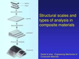
Chapter 19 Plastics and composite Materials: Forming and Shaping. Plastics and composite are relatively easier to handle than metals and require much less force to process them. TABLE 19.1 General Characteristics of Forming and Shaping Processes for Plastics and Composite Materials.

E N D
Chapter 19Plastics and composite Materials: Forming and Shaping
Plastics and composite are relatively easier to handle than metals and require much less force to process them
TABLE 19.1 General Characteristics of Forming and Shaping Processes for Plastics and Composite Materials
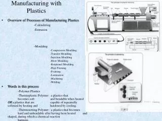
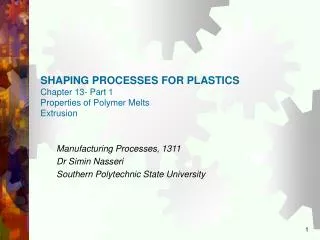
EXTRUSIONmaterial is placed inside a hopper and is fed into the barrel of a screw extruder which has 3 sectionsfeed sectionmelt sectionpumping section
FIGURE 19.2 (a) Schematic illustration of a typical screw extruder. (b) Geometry of an extruder screw. Complex shapes can be extruded with relatively simple and inexpensive dies.
FIGURE 19.4 Extrusion of tubes. (a) Extrusion using a spider die (see also Fig. 15.8) andpressurized air. (b) Coextrusion for producing a parison for a plastic bottle.
FIGURE 19.6 The melt-spinning process for producing polymer fibers, used in a variety of applications, including fabrics and as reinforcements for composite materials; in the stretching box, the right roll rotates faster than the left roll.
INJECTION MOLDINGthe material is fed into the heated cylinder, the melt is forced into the mold , either by a hydraulic plunger or by the rotating screw system of an extruder. After the part is cooled (cured), the molds are opened and the part is ejected
FIGURE 19.7 Schematic illustration of injection molding with (a) a plunger and (b) a reciprocating rotating screw.
FIGURE 19.8 Sequence of operations in the injection molding of a part with a reciprocating screw; this process is used widely for numerous consumer and commercial products, such as toys, containers, knobs, and electrical equipment (see Fig. 19.9).
FIGURE 19.9 Typical products made by injection molding, including examples of insert molding. Source: (a) Courtesy of Plainfield Molding, Inc. (b) Courtesy of Rayco Mold and Mfg. LLC.
FIGURE 19.12 A 2.2-MN (250-ton) injection-molding machine; the tonnage is the force applied to keep the dies closed during the injection of molten plastic into the mold cavities, and hold it there until the parts are cool and stiff enough to be removed from the die. Source: Courtesy of Cincinnati Milacron, Plastics Machinery Division.
COMPRESSION MOLDINGmaterial is placed directly into a heated mold cavity. Forming is done under pressure
FIGURE 19.17 Types of compression molding, a process similar to forging: (a) positive; (b) semipositive; and (c) flash, in which the flash is later trimmed off. (d) Die design for making a compression-molded part with external undercuts.
FIGURE 19.19 Schematic illustration of (a) casting, (b) potting, and (c) encapsulation processes for plastics and for electrical assemblies, where the surrounding plastic serves as a dielectric.
FIBER IMPREGNATIONPREPREGS (FIBERS PRE-IMPREGNATED WITH RESIN)
FIGURE 19.23 (a) Manufacturing process for polymer-matrix composite tape. (b) Boron-epoxy prepreg tape. These tapes are then used in making reinforced plastic parts and components with high strength-to-weight and stiffness-to-weight ratios, particularly important for aircraft and aerospace applications and sports equipment.Source: (a) After T.W. Chou, R.L. McCullough, and R.B. Pipes. (b) Courtesy of Avco Specialty Materials/Textron.
FIGURE 19.24 (a) Single-ply layup of boron-epoxy tape for the horizontal stabilizer for an F-14 fighter aircraft. (b) A 10-axis computer-numerical-controlled tape-laying system; this machine is capable of laying up 75- and 150-mm (3- and 6-in.) wide tapes on contours of up to and at speeds of up to 0.5 m/s (1.7 ft/s).Source: (a) Courtesy of Grumman Aircraft Corporation. (b) Courtesy of The Ingersoll Milling Machine Company.
FIGURE 19.25 Schematic illustration of the manufacturing process for producing fiber-reinforced plastic sheets; the sheet still is viscous at this stage and later can be shaped into various products.Source: After T.-W. Chou, R.L. McCullough, and R.B. Pipes.
FIGURE 19.26 Schematic illustration of (a) vacuum-bag molding and (b) pressure-bagœmolding; these processes are used in making discrete reinforced plastic parts. Source: After T.H. Meister.
FIGURE 19.27 Manual methods of processing reinforced plastics: (a) hand layup and (b) spray layup. Note that, even though the process is slow, only one mold is required. The figures show a female mold, but male molds are used as well; these methods also are called open-mold processing. (c) A boat hull being made by these processes. Source: Courtesy of VEC Technology, LLC.
FIGURE 19.28 (a) Schematic illustration of the filament-winding process; (b) fiberglass being wound over aluminum liners for slide-raft inflation vessels for the Boeing 767 aircraft. The products made by this process have a high strength-to-weight ratio and also serve as lightweight pressure vessels.Source: Courtesy of Brunswick Corporation.
FIGURE 19.32 Examples of design modifications to eliminate or minimize distortion in plastic parts: (a) suggested design changes to minimize distortion; (b) stiffening the bottoms of thin plastic containers by doming, a technique similar to the process used to shape the bottoms of aluminum beverage cans (see Fig. 16.31); and (c) design change in a rib to minimize pull-in (sink mark) caused by shrinkage during the cooling of thick sections in molded parts.
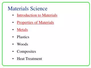
DESIGN CONSIDERATIONS1. The materials involved and their characteristics must be considered, as these properties might be critical to a certain method of production2. Sections shape and thickness must be selected carefully3. Design of parts and dies should be appropriate for a particular shape generation
DESIGN CONSIDERATIONS(continued)4. Large variations in cross sections and thicknesses should be avoided5. Shapes should be selected properly for improved stiffness of the component6. Thermal expansion is an important factor. Improper part design can lead to uneven shrinking
TABLE 19.2 Comparative Production Characteristics of Various Molding Methods