Download
1 / 42
420 likes | 587 Vues
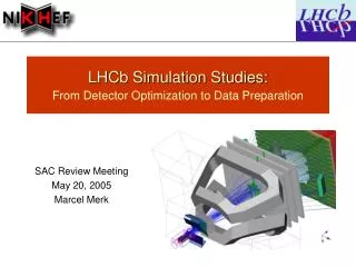
Software for ILD detector simulation and optimization. Akiya Miyamoto KEK 12-July-2010 DESY Computing Seminar. Contentes. ILC overview GLD software tools and optimization ILD Software tools Mokka Reconstruction GRID in KEK. International Linear Collider : ILC. 2004: launched

E N D
Software for ILDdetector simulation and optimization Akiya Miyamoto KEK 12-July-2010 DESY Computing Seminar
Contentes • ILC overview • GLD software tools and optimization • ILD Software tools • Mokka • Reconstruction • GRID in KEK DESY Computing Seminar
International Linear Collider : ILC 2004: launched 2007: ILC RDR 2009: Detector LOI 2012: TDR/DBD e+e- Collider Ecm: 0.2 ~0.5 TeV 1TeV ∫Ldt = 500 fb-1 in 4 years DESY Computing Seminar
Higgs – Vacuum Did Higgs break the symmetry ? Condensed in vacuum ? Higgs coupling proportional to mass in the SM DESY Computing Seminar
Supersymmetry Extending to Higher energy/Early Universe Fermion Boson • Do forces unify ? • Do Quarks and Leptons unify ? • Mass, Coupling DESY Computing Seminar
ILC Reference Design Report Released 2007 summer: http://www.linearcollider.org/cms/?pid=1000437 RDR: 4 volumes/ 774 pages Executive Summary Physics at the ILC Accelerator Detectors DESY Computing Seminar
Challenge of ILC experiments • e+e-Collision:Well defined initial states and relatively clean final states. Find faint new physics signals Make precise tests of theory • Many events contains top, W, Z jets • Precise measurement of jet energy • Calorimeter system inside the coil • Highly segmented calorimeter for high resolution • Efficient b/c tagging crucial • Thin material, strong B field, VTX very close to IP, pixel detectors • Higgs recoil measurements ( e+e- Zh llXh) require good DP/P • Hermetic detector down to very close to beam pipe ( ~ 10 mrad ) • Detector should be shielded well against beam related backgrounds,low energy e+e- pairs, gg hadrons, muons, DESY Computing Seminar
Detectors for ILC experiments Vertex Detector b/c/t tagging Rvtx<1/5 LHC Calorimeter: Neutral particles DE/E <½ of LEP W/Z separation Improves h(c-tag) bad good W Z W Z Higgs recoil to Z Tracker: Charged particles Dpt/pt : 1/10 of LHC DESY Computing Seminar
Challenge of Software DESY Computing Seminar • Challenge • Enrich ILC physics case, taking progresses of HEP ( work with theorists ) • Show the proposed detector can do physics and meet the ILC goal • Performance target • Particle Flow : Very good jet energy resolution by highly segmented calorimeter • Vertexing: 2nd/3rd vertex reconstrucion • Tracking: excellent DP/P in ILC condition • Studies based on full simulation and realistic reconstruction are necessary • Mokka • Marlin Reconstruction • PandoraPFA • LCFIVertex • Track Reconstruction
GLD+LDC ILD LDC: Small cell CAL. Gaseous Tracker 4T European based GLD: Small cell CAL. Gaseous Tracker 3T Asian based DESY Computing Seminar • At the time of ILC RDR, 4 detector concepts were considered. • For LOI submission in 2009, GLD and LDC agrees to merge and formed the ILD group. • In order to define ILD concepts, • studied benchmark processes • checked consistency of software tools • optimized ILD parameters
Event Generator Detector Simulator Event Reconstruction Physics Analysis Beamtest Analysis • Pythia • CAIN • StdHep • QuickSim • FullSim • Digitizer • Finder • Fitter • Jet finder GLD software tools ROOT objects : Event Tree & Configuration • Link to various tools at http://acfahep.kek.jp/subg/sim/soft • GLD Software at http://ilcphys.kek.jp/soft • All packages are kept in the CVS. Accessible from http://jlccvs.kek.jp/ DESY Computing Seminar
JSF • Framework: JSF = Root based application • All functions based on C++, compiled or through CINT • Provides common framework for event generations, detector simulations, analysis, and beam test data analysis • Unified framework for interactive and batch job: GUI, event display • Data are stored as root objects; root trees, ntuples, etc development has started since 1999 • Release includes other tools • QuickSim, • Physsim(event generators) • BSGen(generate luminosity spectrum) • Analysis utilities • … DESY Computing Seminar
Jupiter/Satellites for Full Simulation Studies For real data Tools for simulation Tools Satellites URANUS JUPITER METIS Input/Output module set IO JLC Unified Particle Interaction and Tracking EmulatoR Unified Reconstructionand ANalysis Utility Set Monte-Calro Exact hits To Intermediate Simulated output LEDA Library Extention forData Analysis Geant4 based Simulator JSF/ROOT based Framework MC truth generator Event Reconstruction • Jupiter has modular structure for easy installation of sub-detectors • Jupiter can run as a standalone job or a module of JSF • Geometry parameters are set by an ascII file read-in at run time • Special feature to store pre- and post- point of tracks before/after Calorimeter • and break points for PFA studies DESY Computing Seminar
ILD Optimization Procedure Whizard Physsim Software inter operativity • StdHep: Same generator data • LCIO: Common IO format • GLDPrim/LDCPrim: Similar detector model StdHep LDC GLD MOKKA Jupiter LCIO LCIO helps to collaborative works for detector optimization Marlin Sattelites LCIO After ILD optimization, LDC framework was selected as the baseline for LOI studies. No time to really merge GLD and LDC software DST and Analysis DESY Computing Seminar
Optimization by Benchmark Process by TaikanSuehara • Using several detector models, performance to separate W/Z in jet mode have been studied using SUSY processes No significant differences are seen DESY Computing Seminar
Benchmark : 500 GeV t pair Mokka Mokka Jupiter Jupiter • Only significant difference among detector models found for t full reconstruction, example in t- r-nt p-p0nt • For reconstruction of both g from p0gg • Smaller segmentation (5x5mm2) and larger radius advantageous • Impact on physics sensitivity less pronounced DESY Computing Seminar
ILD Design B=3.5T, RECAL=1.85 m 3x Dbl. Layer VTX Support of BP/VTX/SIT Forward Component Box support option DESY Computing Seminar
ILD LOI and beyond • LOI was submitted March 2009 • Validated by IDAG in September 2009 • Next step is • to develop Detailed Baseline Design (DBD) by 2012 • Re-baseline of ILC, working together with accelerator colleagues DESY Computing Seminar
GDE Schedule DESY Computing Seminar
Software in DBD era DESY Computing Seminar • Guidelines for software related studies given by Research Director • “Develop a realistic simulation model of the baseline design, including faults and limitation” • “Simulate and study updated benchmark processes including 1 TeV, with background conditions and demonstrate physics capabilities” • ILC re-baseline • GDE is updating ILC parameters, taking account R&D progressed since RDR • New parameter will affect beam background conditions and physics performance software based studies are necessary • For ILD • Implementing GLD goodies to LDC and improve LDC soft to meet requirements for DBD ILDsoft • Improve our tools taking into account lessons in LOI era to meet RD’s request
ILD Software tools • Simulation: Mokka • Geant4 application • Digitization DESY Computing Seminar • Generators • Common Stdhep data • Whizard/PhysSim packages • Simulation: Mokka • Geant4 application • Reconstruction • Marlin Framework • Reconstruction tools as Marlin Processors • Core tools • LCIO : standard for persistency format and event data model • Gear, LCCD, CED, … • Grid tools and ilcsoft-install
Mokkasimulation ILD in Mokka by 3D pdf DESY Computing Seminar • Core developped by LLR, using Geant4 • Geometry data are given by MySQL database • “scalable geometry” has been useful for ILD optimization • Many sub-detector configuration co-exists, even for beam-test detectors. • ILD_00 model ILD_n • fairly detailed geometry • Mokka reads • ILC Common Generator samples in stdhep format • GunieaPigbeackground particle data • …. • Mokka outputs • SimCalorimeter, SimTrackerHitsby LCIO
VXD in Mokka Used for ILD-LOI Sensor structure DESY Computing Seminar • Two geometries are available in Mokka • Common to DEPFET, FPCCD, CMOS • Cryostat is present, butcables and sensors are not addressed. to be improved for DBD
Silicon Trackers and TPC • 4 Silicon trackers in ILD: SIT, FTD, ETD, SET • Cylinders/Disks strip sensors for DBD Geometries in Mokka SIT FTD ETD DESY Computing Seminar TPC Gas- Ar/CF4/C4H10 Cu, mylar, G10, Air for Field cage and end plate ( equivalent mass ) No phi-dependence, but OK. TPC is very uniform device
ECAL • Two readout options, sharing same structure: Silicon and Scintillator • SiECAL : baseline for LOI, detailed strcture used for LOI study ECAL module side view : incl. dead spaces SiECAL 5x5mm2 Si ScECAL DESY Computing Seminar Mixed readout ( ScEcal/SiECAL )will be considered in DBD study.
HCAL Cross section of 1 module • Digital HCALActive: RPC 8/16-sided RPC ( cross view) cylindrical Float glass Float Glass Graphite Graphite Mylar 1 layer Mylar Elec. free space PCB spacer • Realistic geometry already implemented in Mokka • Optimizations : • 8/16-sided vs cylindrical & scintillatorvs RPC • thickness ( # layers ), gaps, tail catchers, absorber materials, Analog HCAL Active: Scintilator DESY Computing Seminar
Forward detectors in Mokka ILD CAD model ILD Mokka model BCAL New LCAL driver LHCAL Front view FEchips Tile gap side view of 1 layer DESY Computing Seminar Consists of LCAL, BCAL, LHCAL, Beam tube and Masks Mokka model ~ CAD model, but CAD model will evolve with time and Mokka model needs to follow
Cables/Services Mokka: Inner part of ILD ??? DESY Computing Seminar • Cables, services, dead materialsfor data out/power in/cooling/gas flow • sub-detector drivers implements their own materials. • To address materials in sub-detectorboundaries, small WG has been setup within ILD for • coordination between sub-detectors/optional detectors • defining layout and material budgets Implementation in Mokka will follow • Under new European AIDA framework, new geometry tool kits are in development. New kit will allow consisten geometry treatment among CAD Model, Simulator model, Analysis model. We will be benefitted from this new development
Reconstruction Tools DESY Computing Seminar • Marlin analysis flow • Digitizerfor all sub-detectors • Tracking: • LDCTracking for TPC and VTX/Silicon trackers migration to new C++ version in progress • Particle Flow • Calorimeter clustering • Associate track and calorimeter and create PFObjects ( = primary particles ) • Jet clustering • LCFIVertexing : tag each jets • Output as REC data and DST data by LCIO
Typical feature of ILC events and detector Jet Measurements in ILC Det. Resolution of a ILC detector e+e- Z0 q qbar HD CAL DE/E=50%/√E • Principle of PFA detector • Charged particles by tracking device • Remove charged particle signals in CAL ( avoid double counting ) DE/E(Dp/p) EM CAL DE/E=15%/√E Tracker(TK) Dpt/pt=5x10-5pt Large bore magnet, Large B-field Highly segmented CAL to separate clusters by charged and neutral particles. Patten reconstruction is a key. p(GeV/c)/E(GeV) DESY Computing Seminar
Pandora PFA • Originally developed by Mark Thomson (U. Cam) as a Marlin Processor. • V3.2 was used for ILD LOI. Used by SiD ( thanks to common LCIO format ), • achieved DE/E ~ 25%/√E for Z pole jets • Now re-organized to PandoraPFANew, as a stand alone package PFA algorithm slide by John Marshal (ILD Soft WS) DESY Computing Seminar
LCFIVertexing Pt corrected vertex mass DESY Computing Seminar • LCFI group developed LCFIVertexing package. • Apply algorithm for each jets • It consists of two parts, • ZVTOP/ZVKIN : Find vertexies from probability of overlapped trajectories • NeuralNet for tagging and vertexing • Jet with 1 vertex (=IP) • may contain 1 displaced track (D) • > 1 vertecies: • Pt corrected vertex mass is a very good variable to identify quark floavor. • Other variables (joint-track probability, etc.) • LCFIVertexing also output • vertex charge: powerful discriminator of b and anti-b quarks • Used by both SiD and ILD ( thanks to LCIO )
LCFIVertexing Vertex charge of b-jets in ttbar events Eff. ~ 28% with purity 75% for a b-jet, incl. bB0 DESY Computing Seminar • Typical b/c tag performance • With neural nets tuned for Zqq events • Very good performance ( also thanks to the vertex detector placed very close to IP) • Issues to be studied • performance with beam backgrounds • performance in multi-jet environments
GRID • GRID is an infrastructure for a large scale international researches • GRID provides • Resources for • Large scale computing • Large scale data storage • International/Inter-regional communication basis • GRID have been used extensively in ILD LOI studies • for MC productions • Data sharing between Japan – Germany/France/UK
Network in Japan and GRID Tohoku Univ. • Major HEP projects: • Belle, J-PARC, ATLAS ongoing projects • ILC, Belle2 future projects • Also covering • Material science, bio-chemistry and so on using synchrotron light and neutron source • Radiotherapy as technology transfer • KEK has a role to support university groups in these fields. • including Grid deployment/operation. Nagoya Univ. Kobe Univ. KEK Hiroshima IT Univ. of Tsukuba Hiroshima Univ. (Alice) U of Tokyo (Atlas)
SINET3 http://www.sinet.ad.jp/ Round Trip Time: KEK IHEP/KISTI ~ 100msec FNAL ~ 200msec DESY/IN2P3 ~ 300msec DESY Computing Seminar
GRID infrastructures LCG RENKEI • KEKCC supports both LCG and NAREGI/RENKEI • Many Japanese HEP groups are joining LCG • NAREGI middleware is being deployed as the general purpose e-science infrastructure in Japan • RENKEI is developing a system to provide a seamless user environment between the local resources and multiple grid environment DESY Computing Seminar
GRID for ILC • Two Vos have been used: • CALICE-VO: • Test beam data analysis and MC. Standard data processing in GRID • ILC-VO: • Needs huge CPU resources for the studies. Available only on GRID • Standard MC samples ( ~ 50TB) are on GRID for sharing • Status: • A typical data transfer rate from IN2P3/DESY to KEK: ~ 200kB/sec/port • a frequent timeout for transfer of ~ 2GB: Cured by removing a time out at IN2P3 • Overhead of catalog access • ILD DST: many small size DSTs, limited by CPU time for a MC job. • MC and DST production at DESY/IN2P3 Merge DSTs to create a large size file, then replicated to KEK
A typical GRID performance File transfer: IN2P3 Kobe, 184 files/210 GB in 13 hours - part of ILD LOI study, in Dec. 2008 - 10 ports/job Data size vs Time Transfer rate • Pedestal in transfer time ~ 20~60sec. < 100MB is not effective. • Instantaneous transfer rate: average 4 MB/sec, Max. 10 MB/sec • not great, but has been used for real works successfully During Dec. ‘08 to Feb. ’09, O(10TB) data have been exchanged through GRID. It was crucial for the successful LOI studies.
Recent issues on GRID DESY Computing Seminar • After LOI, KEK has extended GRID resources • CPU: 0.3M SI2K to 6M SI2K ( utilize old CPU resources ) • Storage: IBM HPSS as the backend storage. Tape capacity up to 3 PB.shared by batch server and many other groups. • Operational issues • network speed outside Japan • With increasing WNs, many new problems seems to appear • Files in HPSS : file transfer breaks frequently • Access to MySQL server from WN • Disk space of WNs are not sufficient for storing large temporary data • Over-loaded WMS • Very slow turn around from job submission to job out retrieving Failure rate is not low enough and system tuning is yet to be done.
Summary DESY Computing Seminar • Very extensive developments and studies have been done using ILC software tools. • We are aiming to produce DBD by 2012 and software based study will play crucial role in it. • Our main efforts right now are • updates of simulator models • improvements of core software tools • Improvements of reconstruction tools and new benchmark studies will follow soon