Download
1 / 1
10 likes | 178 Vues
ABSTRACT.

E N D
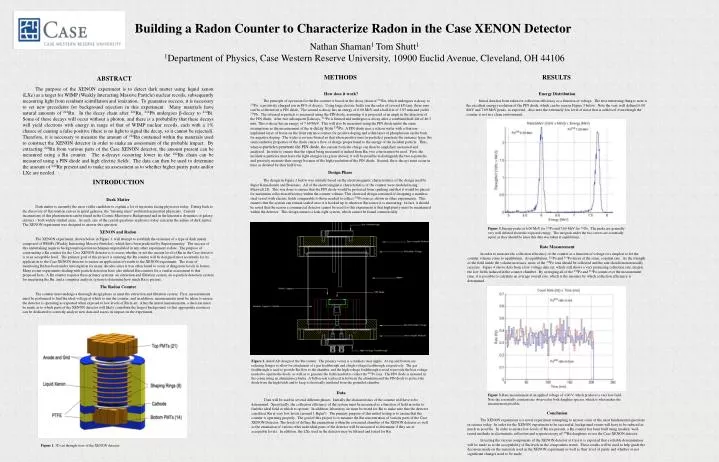
ABSTRACT The purpose of the XENON experiment is to detect dark matter using liquid xenon (LXe) as a target for WIMP (Weakly Interacting Massive Particle) nuclear recoils, subsequently measuring light from resultant scintillation and ionization. To guarantee success, it is necessary to set new precedents for background rejection in this experiment. Many materials have natural amounts of 222Rn. In the decay chain after 222Rn, 214Pb undergoes β-decay to 214Bi. Some of these decays will occur without a photon, and there is a probability that these decays will yield electrons with energy in range of that of WIMP nuclear recoils, each with a 1% chance of causing a false positive (there is no light to signal the decay, so it cannot be rejected). Therefore, it is necessary to measure the amount of 222Rn contained within the materials used to construct the XENON detector in order to make an assessment of the probable impact. By extracting 222Rn from various parts of the Case XENON detector, the amount present can be measured using a Rn counter. The α-decays occurring lower in the 222Rn chain can be measured using a PIN diode and high electric fields. The data can then be used to determine the amount of 222Rn present and to make an assessment as to whether higher purity parts and/or LXe are needed. INTRODUCTION METHODS RESULTS Dark Matter Dark matter is currently the most viable candidate to explain a lot of mysteries facing physicists today. Dating back to the discovery of flat rotation curves in spiral galaxies, the “missing mass” problem has puzzled physicists. Current incarnations of this phenomenon can be found in the Cosmic Microwave Background and in the kinematic dynamics of galaxy clusters – both widely studied areas. As such, one of the central questions in physics today concerns the nature of dark matter. The XENON experiment was designed to answer this question. XENON and Radon The XENON experiment, shown below in Figure 1, will attempt to establish the existence of a type of dark matter composed of WIMPs (Weakly Interacting Massive Particles), which have been predicted by Supersymmetry. The success of this undertaking requires background rejection techniques unparalleled in any other experiment to date. The purpose of constructing a Rn counter for the Case XENON detector is to assess whether or not the current level of Rn in the Case detector is at an acceptable level. The primary goal of this project is ensuring the Rn counter will be designed most accurately for its application to the Case XENON detector to ensure an application of results to the XENON experiment. The issue of monitoring Rn has been under investigation for many decades since it was often found to occur at dangerous levels in homes. Many recent experiments dealing with particle detection have also utilized Rn counters for a similar assessment to that proposed here. A Rn counter requires three primary systems: an extraction and filtration system, an α-particle detection system for measuring the Rn, and a computer analysis system to determine how much Rn is present. The Radon Counter The counter must undergo a thorough design phase as must the extraction and filtration system. First, measurements must be performed to find the ideal voltage at which to run the counter, and in addition, measurements must be taken to ensure the detector is operating as expected when exposed to low levels of Rn in air. After the initial measurements, a decision must be made as to which parts of the XENON detector will likely contribute the largest background, so that appropriate resources can be dedicated to correctly analyze new data and assess its impact on the experiment. How does it work? The principle of operation for the Rn counter is based on the decay chain of 222Rn, which undergoes α-decay to 218Po, a positively charged ion in 88% of decays. Using large electric fields (on the order of several kV/cm), these ions can be collected on a PIN diode. The second α-decay has an energy of 6.00 MeV and a half-life of 3.05 min and yields 214Pb. The released α-particle is measured using the PIN diode, assuming it is projected at an angle in the direction of the PIN diode. After two subsequent β-decays, 214Po is formed and undergoes α-decay after a combined half-life of 46.5 min. This α-decay has an energy of 7.69 MeV. This will also be measured using the PIN diode under the same assumptions as the measurement of the α-decay from 218Po. A PIN diode uses a silicon wafer with a thin ion-implanted layer of boron on the front entrance contact for positive doping and a thin layer of phosphorous on the back for negative doping. The wafer is reverse-biased so that when positive ions (α-particles) penetrate the entrance layer, the semiconductor properties of the diode cause a flow of charge proportional to the energy of the incident particle. Thus, when α-particles penetrate the PIN diode, the current from the charge can then be amplified, measured and analyzed. In order to ensure that the signal being measured is indeed from Rn, two criteria must be used. First, the incident α-particles must have the right energies (as given above); it will be possible to distinguish the two α-particles and precisely measure their energy because of the high resolution of the PIN diode. Second, the α-decays must occur in time as dictated by their half-lives. Design Phase The design in Figure 2 below was initially based on the electromagnetic characteristics of the design used by Super Kamiokande and Borexino. All of the electromagnetic characteristics of the counter were modeled using Maxwell 2D. This was done to ensure that the PIN diode would be protected from sparking and that it would be placed for maximum collection efficiency within the counter volume. This electrical design consisted of designing a stainless steel vessel with electric fields comparable to those needed to collect 218Po ions as shown in other experiments. This ensures that the system can remain sealed once it is hooked up to whatever Rn source it is measuring. In fact, it should be noted that the reason a commercial detector cannot be used for this experiment is that high purity must be maintained within the detector. This design ensures a leak-tight system, which cannot be found commercially. Energy Distribution Initial data has been taken for collection efficiency as a function of voltage. The first interesting thing to note is the excellent energy resolution of the PIN diode, which can be seen in Figure 3 below. Note the very well defined 6.00 MeV and 7.69 MeV peaks, as expected. Also note the extremely low level of noise that is achieved, even though the counter is not in a clean environment. Figure 3. Energy peaks at 6.00 MeV for 218Po and 7.69 MeV for 214Po. The peaks are generally very well defined about the expected energy. The integrals under the two curves are essentially equal, as they should be since this data was taken at equilibrium. Figure 2. AutoCAD design of the Rn counter. The primary vessel is a stainless steel nipple. At top and bottom are reducing flanges to allow for attachment of a gas feedthrough and a high-voltage feedthrough, respectively. The gas feedthrough is used to provide Rn flow to the chamber, and the high-voltage feedthrough is used to provide the bias voltage needed to operate the diode, as well as to generate the fields needed to collect the 218Po ions. The PIN diode is mounted in the center using an aluminum cylinder. A Teflon seat is placed in between the aluminum and the PIN diode to protect the diode from the high fields and to keep it electrically insulated from the grounded chamber. Figure 3. Rate measurement at an applied voltage of -100 V, which produces a very low field. Note the essentially constant rate observed in both daughter species, which is what makes the measurement possible. Figure 1. 3D cut through view of the XENON detector Building a Radon Counter to Characterize Radon in the Case XENON Detector Nathan Shaman1Tom Shutt1 1Department of Physics, Case Western Reserve University, 10900 Euclid Avenue, Cleveland, OH 44106 Rate Measurement In order to measure the collection efficiency of the counter as a function of voltage it is simplest to let the counter volume come to equilibrium. At equilibrium, 218Po and 214Po decay at the same, constant rate. As the strength of the field inside the volume increases, more of the 218Po ions should be collected and the rate should monotonically increase. Figure 4 shows data from a low voltage data set, which still shows a very promising collection rate, despite the low fields induced in the counter chamber. By averaging all of the 218Po and 214Po counts over the measurement time, it is possible to calculate an average overall rate, which is the measure by which collection efficiency is determined. Data Data will be used in several different phases. Initially the characteristics of the counter will have to be determined. Specifically, the collection efficiency of the system must be measured as a function of field in order to find the ideal field at which to operate. In addition, laboratory air must be tested for Rn to make sure that the detector can detect Rn at very low levels (around 1 Bq/m3). The primary purpose of this initial testing is to ensure that the counter is operating properly. The goal of this project is to measure the Rn concentration of various parts of the Case XENON Detector. The levels of diffuse Rn emanations within the evacuated chamber of the XENON detector as well as the emanation of various other individual parts of the detector will be measured to determine if they are at acceptable levels. In addition, the LXe used in the detector may be filtered and tested for Rn. Conclusion The XENON experiment is a novel experiment attempting to answer some of the most fundamental questions in science today. In order for the XENON experiment to be successful, background events will have to be reduced as much as possible. In order to ensure low levels of Rn are present, a Rn counter has been built using modern, well-tested methods in electrostatic collection and α spectroscopy of 222Rn daughters to test the Case XENON detector. In testing the various components of the XENON detector at Case it is expected that a reliable determination will be made as to the acceptability of Rn levels in the components tested. These results will be used to help guide the decisions made on the materials used in the XENON experiment as well as their level of purity and whether or not significant changes need to be made.