Download
1 / 16
170 likes | 474 Vues
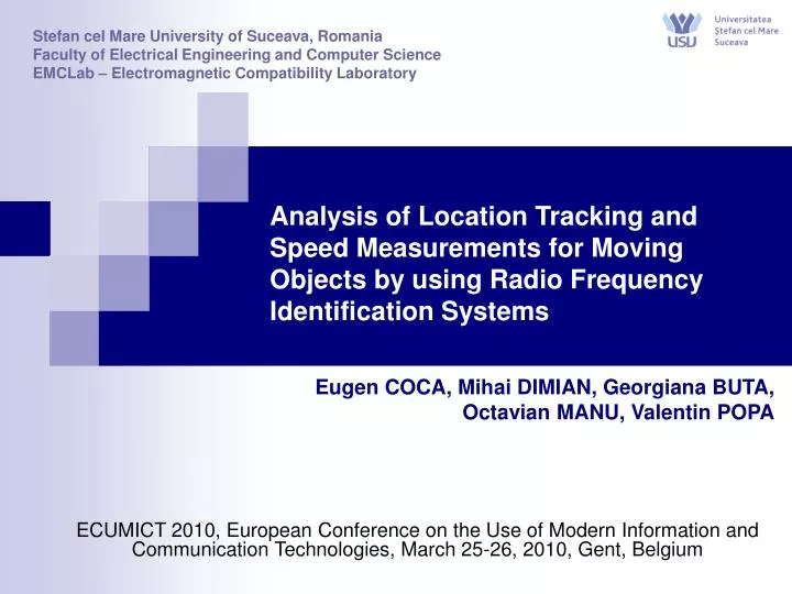
Stefan cel Mare University of Suceava, Romania Faculty of Electrical Engineering and Computer Science EMCLab – Electromagnetic Compatibility Laboratory. Analysis of Location Tracking and Speed Measurements for Moving Objects by using Radio Frequency Identification Systems.

E N D
Stefan cel Mare University of Suceava, Romania Faculty of Electrical Engineering and Computer Science EMCLab – Electromagnetic Compatibility Laboratory Analysis of Location Tracking and Speed Measurements for Moving Objects by using Radio Frequency Identification Systems ECUMICT 2010, European Conference on the Use of Modern Information and Communication Technologies, March 25-26, 2010, Gent, Belgium Eugen COCA, Mihai DIMIAN, Georgiana BUTA, Octavian MANU, Valentin POPA
Introduction • Performance evaluation of an ultra-high frequency (UHF, 865-945 MHz) RFID system • Radiated emissions measurements according to EN 55022 standard • Speed measurements methods based onTime of Arrival (TOA) and Angle of Arrival (AOA) • Experimental Results • Conclusions
3 1 2 EMITTING ANTENNA RECEIVING ANTENNA RECEIVING ANTENNA COAXIAL CABLES RFID READER COMPUTER RS232 RFID READER = RF MODULE + DSP MODULE The received RF signals are demodulated and sent to DSP module for processing 1. Performance evaluation • UHF (865-945 MHz) RFID system Fig. 1 – UHF RFID system (configuration)
1. Performance evaluation • UHF (865-945 MHz) RFID system Receiving antennas Emitting antenna Receiving antennas Emitting antenna READER Module Fig. 2 – UHF RFID system (photos)
1. Performance evaluation • UHF (865-945 MHz) RFID system 5 uW stick Ecotag 5 uW claymore Ecotags 200 uW Ecochiptags (credit card format) Fig. 3 - UHF RFID system - transponders
2. Radiated Emissions Measurements SHIELDED ROOM • Test setup TURN TABLE (3600 ROTATION) LOG-PERIODIC ANTENNA E R R RFID Reader (at 0.8 m) EUT (Equipment Under Test) RF CABLE TEST TABLE measurement distance = 3 m ANECHOIC CHAMBER Figure 4 – Test Setup for Radiated Emissions Measurements (anechoic chamber)
2. Radiated Emissions Measurements • The CISPR22 standard limit = 47 dB(uV/m) Radiated emission levels >> 47 dB(uV/m) measurement distance = 3 m Table 1 – Example of radiated emissions levels (30-1000 MHz frequency band)
2. Radiated Emissions Measurements • Experimental results The RFID Radar radiated emissions levels (measured in the anechoic chamber) As we might see in table 1, the radiation emissions levels measured using the test setup described in figure 4, exceed the limits defined in EN 55022 standard (CISPR22). Therefore, the RFID system considered has relatively high emission levels for the main operating frequency band. This leads to electromagnetic interferences for electrical equipments operating nearby and raises human safety issues. The limit defined in EN 55022 standard for the 230 MHz - 1000 MHz frequency band Table 2 - Radiated Emissions Levels (30-1000 MHz frequency band)
3. The K-band radar • Bushnell Velocity Speed Gun Technical specifications Figure 5 - The K-band radar
P2 d12 d2 α2 α12 P1 d1 x α1 O 4. Speed Measurements • The method for measuring the transponder speed is based on the Time of Arrival and Angle of Arrival information provided by the RFID radar (d1, α1, t1) and (d2, α2, t2) = (distance, angle, time) information provided by the radar for two consecutive readings P1 and P2 of a transponder in range Fig. 6 - Speed measurements
4. Speed Measurements • The signal transmitted between the receiving antennas preprocessor and the digital processing board located inside the reader 1 transponder the time spacing between two transponder transmissions is about 333 milliseconds Fig. 7 - The signal received by the RFID Radar when only one transponder unit is in the active area
4. Speed Measurements • The signal transmitted between the receiving antennas preprocessor and the digital processing board located inside the reader 4 transponders Fig. 8 - The signal received by the RFID Radar when four transponder units are in the active area
4. Speed Measurements • The speed measurement system was tested using also passive and active transponders Computer (system command) The speed measured using our software (38 km/h) is almost equal with the K-band Radar indication (36 km/h) Emission antenna Speed measurement (software) Fig. 9 – Experimental results K-band Radar
4. Speed Measurements The repeatability of the measurements was tested outdoor by performing 50 measurements of the transponder moving with 10 km/h for each of the following distances: 20m, 30m and 40m Table 3: Maximum measured speed as a function of the distance between the transponder and the antenna system Table 4: Repeatability of the measurements
Conclusions • We presented a performance evaluation of an ultra-high frequency (UHF, 865-945 MHz) RFID system with respect to location tracking of moving objects • Several radiated emissions measurements were made in order to point out the high perturbations levels of UHF RFID radar • We developed a method for measuring the transponder speed - based on the Time of Arrival (TOA) and Angle of Arrival (AOA) information provided by the RFID radar • The RFID Radar method performed reasonable well when compared against classical K-band Radar, and proved that an additional capability could be added to the current RFID system that mainly focus on transponder localization and information transfer
Thank You ! CONTACT EMCLab - Electromagnetic Compatibility LaboratoryEN 17025 Accreditedwww.emclab.eu