Download
1 / 17
170 likes | 356 Vues
CO 2 Cooling for PXD/SVD. IDM Meeting. Talk Outline. CO 2 History How to use CO 2 for cooling Cooling system layouts Requirements for SVD II CO 2 merits Costs Maintenance Timeline. CO 2 History. 1866: first reported CO 2 cooling system was built (dry out)

E N D
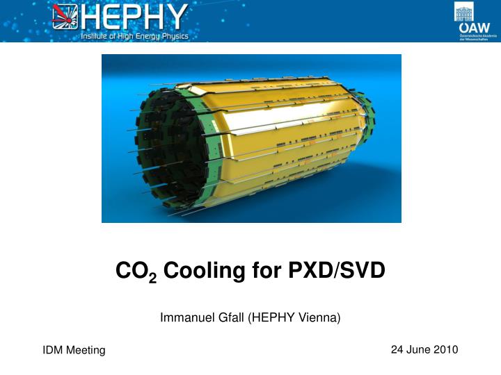
CO2 Cooling for PXD/SVD Immanuel Gfall (HEPHY Vienna) IDM Meeting
Talk Outline • CO2 History • How to use CO2 for cooling • Cooling system layouts • Requirements for SVD II • CO2 merits • Costs • Maintenance • Timeline Immanuel Gfall (HEPHY Vienna)
CO2 History • 1866: first reported CO2 cooling system was built (dry out) • Until 1930: Wide spread development and use of CO2 systems • 1930: CFC/ HCFC era starts and pushes CO2 to extinction • 1988: first patent draft for transcritical CO2 system • 1992: first experimental data on mobile AC system published • 2000: TU Dresden introduces a CO2 powered heat pump • 2001: Commercial introduction of R744 hot water heat pumps in Japan • 2009: Fully operational CO2 cooling system at CERN (Velo Detector/ LHCb) • CO2 is the refrigerant of choice for future detector upgrades (CMS Pixel, ATLAS Pixel, …) Immanuel Gfall (HEPHY Vienna)
Mollier Chart (log p-H) Gas Temperature Gas Density Entropy Saturation Line Immanuel Gfall (HEPHY Vienna)
Working Principle • Cooling effect of boiling fluid is used! • Boiling and evaporation is established through enthalpy change of the working fluid and pressure reduction • This enthalpy change is supplied by a heat source (read out chips) • The dissipated power of a heat source and the change of enthalpy are correlated: • For ideal processes the power dissipated by the source = power absorbed by the fluid • This process is different from single phase cooling cycles Immanuel Gfall (HEPHY Vienna)
CO2 Basic Cooling Cycle • CO2 can be operated as a transcritical or subcritical cycle • Heat is emitted in a condenser to reduce the fluids enthalpy • Pressure reduction leads to temperature change of fluid • Fluid is evaporated under constant pressure • This stage is used to absorb heat • Compressor is used to increase pressure to restart the cycle Pressure Reduction Heat Exchange c d a Compression b Cooling Immanuel Gfall (HEPHY Vienna)
Issues with Compressor Cycle • Compressor needs gas on suction side • Heater is required to ensure fully evaporated fluid • Warm supply line for liquid cooling fluid is possible • Additional heater is required for warm return line • Oil free compressor is needed! Temperature Regulation Heater Compressor Condenser Heat Load Pressure Reduction Heat Exchanger Immanuel Gfall (HEPHY Vienna)
2-Phase Accumulator Controlled Loop • Accumulator regulates pressure • Accumulator ensures liquid CO2 at suction side of the pump • Membrane pump used instead of compressor • A pump pressurizes the fluid and propels it • Internal heat exchangerwarms up sub cooled fluid before pressure reduction • Fluid never changes to purelygaseous state Immanuel Gfall (HEPHY Vienna)
2PACL LHCb Design • Chiller is used to cool CO2 • Accumulator is the process controlling element • Concentric heat exchanger tube used to warm up liquid CO2 up to the saturation point • Picture demonstrates LHCb Velo layout Immanuel Gfall (HEPHY Vienna)
Cooling Unit Components Lewa Pump Reinforced Heat Changer CO2 closed cycle test plant from Hans Postema Immanuel Gfall (HEPHY Vienna)
Compressor vs. Accumulator • Traditional cooling process passes through the dry-out zone • Potential damage of electronics • 2PACL design avoids dry out zone intrinsically Immanuel Gfall (HEPHY Vienna)
Cooling Requirements • Smallest possible material budget in the acceptance region • Operating temperature @ -20°C for SNR improvement • Radiation hard coolant • Cooling system needs to handle 1kW+ of dissipated heat (including PXD) • Cooling fluid should be dielectric, non-flammable, non-toxic and non-corrosive 05.04.2010 Immanuel Gfall (HEPHY Vienna) Immanuel Gfall (HEPHY Vienna) 12
Cooling Boundary Conditions • Power dissipation/APV: 0.4 W • 1 Origami sensor features 10 APVs • Total Origami power dissipation: 356 W • 404 W dissipated at the hybridboards • Total SVD power dissipation: 760 W 05.04.2010 Immanuel Gfall (HEPHY Vienna) Immanuel Gfall (HEPHY Vienna) 13
d=3.6mm d=0.9mm T = 0.07mm T = 0.12mm CO2 Merits • CO2 fulfills the requirements • Low material budget inside acceptance region (CO2 has a long radiation length) • Thinner tubes required compared to other cooling fluids • Small temperature gradient over long lines • Fast temperature regulation capacity • Supreme heat capacity and transport • Cooling process requires low mass flow • Radiation hard • CO2 is cheap an easily available CuNi Tubes! Immanuel Gfall (HEPHY Vienna)
Costs • Cooling plant • Piping and additional components • Test unit and test setups • Construction costs • Total: ~17 million Yen (~160k €) Immanuel Gfall (HEPHY Vienna)
Maintenance • Maintenance schedule: every year • Relatively passive system = little work to do • Pump is the only service part • Check connectors and valves for leaks • CO2 level check is automated • CO2 can easily be re-filled on demand Immanuel Gfall (HEPHY Vienna)
Outlook • New team member in Vienna to tackle CO2 blow system setup • CO2 blow system development until December 2010 • SVD/PXD mockup until December 2010 • Early 2011: Cooling tests with mockup • 2011: Design and development of CO2 cooling plant control system • 2012: Construction and test of CO2 cooling plant Immanuel Gfall (HEPHY Vienna)