Download

1 / 45
500 likes | 694 Vues
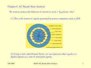
Chapter 11 AC Steady-State Power. Matching Network for Maximum Power Transfer. Cellular Telephone. Design the matching network to transfer maximum power to the load where the load is the model of an antenna of a wireless communication system. George Westinghouse, 1846-1914.

E N D
Matching Network for Maximum Power Transfer Cellular Telephone Design the matching network to transfer maximum power to the load where the load is the model of an antenna of a wireless communication system.
George Westinghouse, 1846-1914 The greatest engineer of his day, George Westinghouse modernized the railroad industry and established the electric power system. Nikola Tesla, 1856-1943 Tesla was responsible for many inventions, including the ac induction motor, and was a contributor to the selection of 60Hz as the standards ac frequency in the United States.
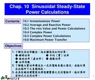
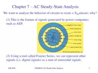
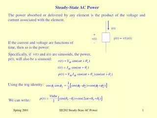
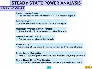
Instantaneous Power and Average Power Instantaneous Power A circuit element If v(t) is a periodic function Then for a linear circuit i(t) is also a periodic function
Instantaneous Power and Average Power(cont.) Average Power Arbitrary point in time If v(t) is a sinusoidal function For a linear circuit i(t) is also a sinusoidal function
average value of the cosine function over a complete period iszero
Example 11.3-1 P = ? Using the period from t = 0 to t = T i(t) through aresistor R The instantaneous power is The average power is
Example 11.3-2 PL= ? PR= ? The element voltages are The average power delivered by the voltage source is The average power delivered to the voltage source is
Example 11.3-2 (cont.) The average power delivered to the resistor is The average power delivered to the inductor is WHY the average power delivered to the inductor = 0 ? The angle of vLalways be larger than the angle of iL and
Effective Value of a Periodic Waveform The goal is to find a dc voltage, Veff (or dc current, Ieff), for a specified vs(t) that will deliver the same average power to R as would be delivered by the ac source. The energy delivered in a period T is The average power delivered to the resistor by a periodic current is
Effective Value of a Periodic Waveform (cont.) The power delivered by a direct current is Solve for Ieff rms = root-mean-square The effective value of a current is the steady current (dc) that transfer the same average power as the given time varying current.
Example 11.4-1 Ieff= ? Express the waveform over the period of t = 0 to t = T i(t) = sawtooth waveform
Complex Power A linear circuit is excited by a sinusoidal input and the circuit has reached steady state. The element voltage and current can be represented in (a) the time domain or (b) the frequency domain
Complex Power (cont.) To calculate average power from frequency domain representation of voltage and current i.e. their phasors The complex power delivered to the element is defined to be Apparent power
Complex Power (cont.) The complex power in rectangular form is or real or average power reactive power Volt-Amp Volt-Amp Reactive
Complex Power (cont.) The impedance of the element can be expressed as In rectangular form or resistance reactance
Complex Power (cont.) The complex power can also be expressed in terms of the impedance
Complex Power (cont.) The impedance triangle The complex power triangle The complex power is conserved The sum of complex power absorbed by all elements of a circuit is zero.
Complex Power (cont.) The complex power is conserved implies that both average power and reactive power are conserved. or
Example 11.5-1 S is conserved ? Solving for the mesh current Use Ohm’s law to get the element voltage phasors
Example 11.5-1 (cont.) Consider the voltage source supplied by the source For the resistor absorbed by the resistor For the inductor delivered to the inductor
Example 11.5-1 (cont.) For the capacitor delivered to the capacitor The total power absorbed by all elements (except source) For all elements
Example 11.5-2 P is conserved ? The average power for the resistor, inductor, and capacitor is The average power supplied by the voltage source is
Power Factor The ratio of the average power to the apparent power is called the power factor(pf). average power apparent power Therefore the average power
Power Factor (cont.) The cosine is an even function Need additional information in order to find the angle Ex The transmission of electric power Time domain
Power Factor (cont.) Frequency domain We will adjust the power factor by adding compensating impedance to the load. The objective is to minimize the power loss (i.e. absorbed) in the transmission line. The line impedance
Power Factor (cont.) The average power absorbed by the line is The customer requires average power delivered to the load P at the load voltage Vm Solving for Im max pf =1
Power Factor (cont.) compensating impedance A compensating impedance has been attached across the terminals of the customer’s load. corrected The load impedance is and the compensating impedance is We want ZC to absorb no average power so
Power Factor (cont.) The impedance of the parallel combination ZP The power factor of the new combination Calculate for RP and XP
Power Factor (cont.) From Solving for XC Typically the customer’s load is inductive ZC = capacitive
Power Factor (cont.) Solving for Let where
Example 11.6-1 I and pf = ? Load = 50 kW of heating (resistive) and motor 0.86 lagging pf Load 1 50 kW resistive load Load 2 motor 0.86 lagging pf Q P
Example 11.6-1 (cont.) To calculate the current
Example 11.6-2 pf ==> 0.95, 1 C = ? We wish to correct the pf to be pfc
Example 11.6-2 (cont.) Or use
The Power Superposition Principle (cont.) Let the radian frequency of the 1st source = mw and the radian frequency of the 2nd source = nw integer
The Power Superposition Principle (cont.) For the case that m and nare not integer for example m = 1, n = 1.5
The Power Superposition Principle (cont.) The superposition of average power The average power delivered to a circuit by several sinusoidal sources, acting together, is equal to the sum of the average power delivered to the circuit by each source acting alone, if and only if, no two of the source have the same frequency. If two or more sources are operating at the same frequency the principle of power superposition is not valid but the principle of superposition remains valid. For N sources
Example 11.7-1(cont.) Case I These phasors correspond to different frequencies and cannot be added. Using the superposition The average power can be calculated as Since the two sinusoidal sources have different frequencies
Example 11.7-1(cont.) Case II Both phasors correspond to the same frequency and can be added. The sinusoidal current is The average power can be calculated as Power superposition cannot be used here because Both sources have same frequencies
The Maximum Power Transfer Theorem We wish to maximize P set
Coupled Inductors (b) one coil current enters the dotted end of the coil, but the other coil current enters the undotted end • both coil currents enter • the dotted ends of the coils
Summary • Instantaneous Power and Average Power • Effective Value of a Periodic Waveform • Complex Power • Power Factor • The Power Superposition Principle • The Maximum Power Transfer Theorem • Coupled Inductor and Transformer