Download
1 / 1
10 likes | 121 Vues
Internal rotation Ω(r,Θ) (0<r<R). Internal rotation Ω(r,Θ) (0<r<R). Global Helioseismology Processing. Tachocline. HMI Processing Pipeline and Standard Data Products. Meridional Circulation. Internal sound speed, c s (r,Θ) (0<r<R). Internal sound speed, c s (r,Θ) (0<r<R). GSFC.

E N D
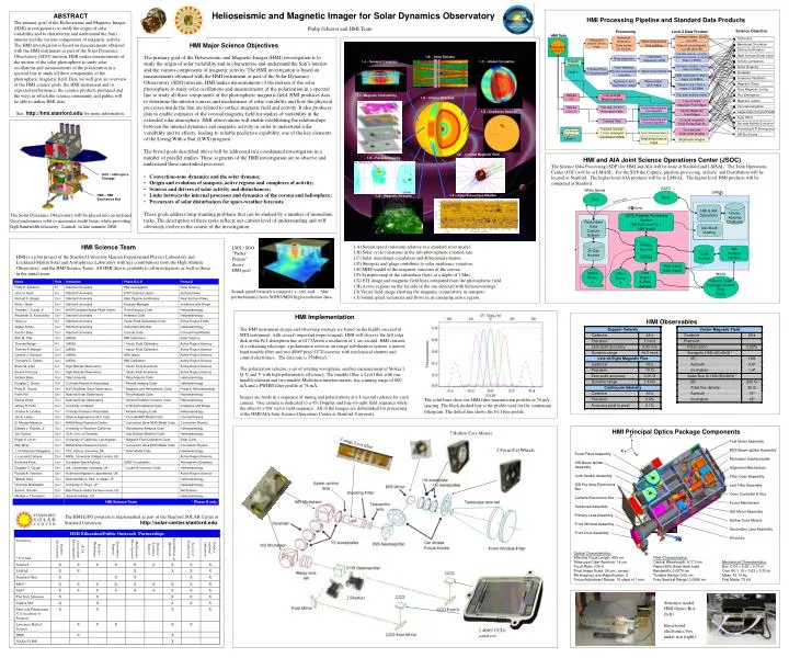
Internal rotation Ω(r,Θ) (0<r<R) Internal rotation Ω(r,Θ) (0<r<R) Global Helioseismology Processing Tachocline HMI Processing Pipeline and Standard Data Products Meridional Circulation Internal sound speed, cs(r,Θ) (0<r<R) Internal sound speed, cs(r,Θ) (0<r<R) GSFC HMI Data Processing Data Product Science Objective White Sands Differential Rotation LMSAL MOC Processing Level 2 Data Product Full-disk velocity, v(r,Θ,Φ), And sound speed, cs(r,Θ,Φ), Maps (0-30Mm) Full-disk velocity, v(r,Θ,Φ), And sound speed, cs(r,Θ,Φ), Maps (0-30Mm) DDS Near-Surface Shear Layer House- keeping Database HMI Data Local Helioseismology Processing housekeeping Spherical Harmonic Time series To l=1000 Filtergrams Activity Complexes Heliographic Doppler velocity maps Filtergrams Mode frequencies And splitting HMI Major Science Objectives Stanford HMI & AIA Operations Carrington synoptic v and cs maps (0-30Mm) Carrington synoptic v and cs maps (0-30Mm) Active Regions Level-0 JSOC Pipeline Processing System HMI/AIA Level-0, 1, HMI-level2 Sunspots • The primary goal of the Helioseismic and Magnetic Imager (HMI) investigation is to study the origin of solar variability and to characterize and understand the Sun’s interior and the various components of magnetic activity. The HMI investigation is based on measurements obtained with the HMI instrument as part of the Solar Dynamics Observatory (SDO) mission. HMI makes measurements of the motion of the solar photosphere to study solar oscillations and measurements of the polarization in a spectral line to study all three components of the photospheric magnetic field. HMI produces data to determine the interior sources and mechanisms of solar variability and how the physical processes inside the Sun are related to surface magnetic field and activity. It also produces data to enable estimates of the coronal magnetic field for studies of variability in the extended solar atmosphere. HMI observations will enable establishing the relationships between the internal dynamics and magnetic activity in order to understand solar variability and its effects, leading to reliable predictive capability, one of the key elements of the Living With a Star (LWS) program. • The broad goals described above will be addressed in a coordinated investigation in a number of parallel studies. These segments of the HMI investigation are to observe and understand these interlinked processes: • Convection-zone dynamics and the solar dynamo; • Origin and evolution of sunspots, active regions and complexes of activity; • Sources and drivers of solar activity and disturbances; • Links between the internal processes and dynamics of the corona and heliosphere; • Precursors of solar disturbances for space-weather forecasts. • These goals address long-standing problems that can be studied by a number of immediate tasks. The description of these tasks reflects our current level of understanding and will obviously evolve in the course of the investigation. 1.B – Solar Dynamo High-resolution v and cs maps (0-30Mm) High-resolution v and cs maps (0-30Mm) Local wave frequency shifts Ring diagrams Redundant Data Capture System Irradiance Variations 1.J – Sunspot Dynamics 1.C – Global Circulation Doppler Velocity Quicklook Viewing Doppler Velocity Magnetic Shear Deep-focus v and cs maps (0-200Mm) Deep-focus v and cs maps (0-200Mm) Time-distance Cross-covariance function Tracked Tiles Of Dopplergrams Wave travel times Level-1 Observables Flare Magnetic Config. Far-side activity index Far-side activity index Flux Emergence Primary Archive Line-of-sight Magnetograms 30-Day Archive Egression and Ingression maps Wave phase shift maps Local Archive AIA Analysis System Magnetic Carpet Line-of-Sight Magnetic Field Maps Line-of-Sight Magnetic Field Maps Catalog Coronal energetics 1.I – Magnetic Connectivity Vector Magnetograms Stokes I,V Line-of-sight Magnetograms 1.A – Interior Structure Vector Magnetic Field Maps Vector Magnetic Field Maps Large-scale Coronal Fields High-Level Data Import Z Solar Wind Offline Archive Stokes I,Q,U,V Full-disk 10-min Averaged maps Vector Magnetograms Fast algorithm Coronal magnetic Field Extrapolations Coronal magnetic Field Extrapolations Data Export & Web Service World Continuum Brightness Offsite Archive 1.D – Irradiance Sources Far-side Activity Evolution X Science Team Forecast Centers EPO Public Y Predicting A-R Emergence Coronal and Solar wind models Coronal and Solar wind models Vector Magnetograms Inversion algorithm Tracked Tiles IMF Bs Events Brightness Images Brightness Images Tracked full-disk 1-hour averaged Continuum maps Continuum Brightness Solar limb parameters Level-1 Brightness feature maps HOP – HMI Optics Package 1.E – Coronal Magnetic Field HMI and AIA Joint Science Operations Center (JSOC) The Science Data Processing (SDP) for HMI and AIA will be done at Stanford and LMSAL. The Joint Operations Center (JOC) will be at LMASL. For the SDP the Capture, pipeline processing, archive, and Distribution will be located at Stanford. The higher level AIA products will be at LMSAL. The higher level HMI products will be computed at Stanford. 1.H – Far-side Imaging HEB – HMI Electronics Box 1.F – Solar Subsurface Weather 1.G – Magnetic Stresses 1.A) Sound speed variations relative to a standard solar model. 1.B) Solar cycle variations in the sub-photospheric rotation rate. 1.C) Solar meridional circulation and differential rotation. 1.D) Sunspots and plage contribute to solar irradiance variation. 1.E) MHD model of the magnetic structure of the corona. 1.F) Synoptic map of the subsurface flows at a depth of 7 Mm. 1.G) EIT image and magnetic field lines computed from the photospheric field. 1.H) Active regions on the far side of the sun detected with helioseismology. 1.I) Vector field image showing the magnetic connectivity in sunspots. 1.J) Sound speed variations and flows in an emerging active region. LWS / SDO “Poster Picture” shows HMI goal Sound-speed beneath a sunspot ( +, red, and -, blue perturbations) from SOHO/MDI high-resolution data. HMI Observables Fold Mirror Assembly BDS Beam-splitter Assembly Michelson Interferometer Alignment Mechanism Filter Oven Assembly Lyot Filter Assembly Oven Controller E-Box Focus Mechanism ISS Mirror Assembly Hollow Core Motors Secondary Lens Assembly Structure Focal Plane Assembly ISS Beam-splitter Assembly Limb Sensor Assembly ISS Pre-Amp Electronics Box Camera Electronics Box Telescope Assembly Primary Lens Assembly Front Window Assembly Front Door Assembly Optical Characteristics: Effective Focal Length: 495 cm Telescope Clear Aperture: 14 cm Focal Ratio: f/35.4 Final Image Scale: 24 µm / arcsec Re-imaging Lens Magnification: 2 Focus Adjustment Range: 16 steps of 1 mm Filter Characteristics: Central Wavelength: 617.3 nm Reject 99% Solar Heat Load Bandwidth: 0.0076 nm Tunable Range: 0.05 nm Free Spectral Range: 0.0688 nm Mechanical Characteristics: Box: 0.84 × 0.55 × 0.16 m Over All: 1.19 × 0.83 × 0.30 m Mass: 42.15 kg First Mode: 73 Hz Helioseismic and Magnetic ImagerforSolar Dynamics Observatory ABSTRACT The primary goal of the Helioseismic and Magnetic Imager (HMI) investigation is to study the origin of solar variability and to characterize and understand the Sun's interior and the various components of magnetic activity. The HMI investigation is based on measurements obtained with the HMI instrument as part of the Solar Dynamics Observatory (SDO) mission. HMI makes measurements of the motion of the solar photosphere to study solar oscillations and measurements of the polarization in a spectral line to study all three components of the photospheric magnetic field. Here we will give an overview of the HMI science goals, the HMI instrument and its expected performance, the science products produced and the ways in which the science community and public will be able to utilize HMI data. See:http://hmi.stanford.edufor more information. Philip Scherrer and HMI Team The Solar Dynamics Observatory will be placed into an inclined Geosynchronous orbit to maximize sunlit hours while providing high bandwidth telemetry. Launch in late summer 2008. HMI Science Team HMI is a joint project of the Stanford University Hansen Experimental Physics Laboratory and Lockheed-Martin Solar and Astrophysics Laboratory with key contributions from the High Altitude Observatory, and the HMI Science Team. All HMI data is available to all investigators as well as those in the initial team. HMI Implementation The HMI instrument design and observing strategy are based on the highly successful MDI instrument, with several important improvements. HMI will observe the full solar disk in the Fe I absorption line at 6173Åwith a resolution of 1 arc-second. HMI consists of a refracting telescope, a polarization selector, an image stabilization system, a narrow band tunable filter and two 4096² pixel CCD cameras with mechanical shutters and control electronics. The data rate is 55Mbits/s. The polarization selector, a set of rotating waveplates, enables measurement of Stokes I, Q, U and V with high polarimetric efficiency. The tunable filter, a Lyot filter with one tunable element and two tunable Michelson interferometers, has a tuning range of 600 mÅ and a FWHM filter profile of 76 mÅ. Images are made in a sequence of tuning and polarizations at a 4-second cadence for each camera. One camera is dedicated to a 45s Doppler and line-of-sight field sequence while the other to a 90s vector field sequence. All of the images are downlinked for processing at the HMI/AIA Joint Science Operations Center at Stanford University. The solid lines show the HMI filter transmission profiles at 76 mÅ spacing. The black dashed line is the profile used for the continuum filtergram. The dotted line shows the Fe I line profile. HMI Principal Optics Package Components 7 Hollow Core Motors 5 stage Lyot filter 2 Focus/Cal Wheels The HMI E/PO program is implemented as part of the Stanford SOLAR Center at Stanford University. http://solar-center.stanford.edu 2 Shutters Structure model HMI Optics Box (left) Brassboard electronics box under test (right). 2 40962 CCDs actual size