Download
1 / 41
410 likes | 415 Vues
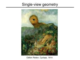
Geometry of a single camera. Odilon Redon, Cyclops , 1914. Our goal: Recovery of 3D structure. J. Vermeer , Music Lesson , 1662.

E N D
Geometry of a single camera Odilon Redon, Cyclops, 1914
Our goal: Recovery of 3D structure J. Vermeer,Music Lesson, 1662 A. Criminisi, M. Kemp, and A. Zisserman,Bringing Pictorial Space to Life: computer techniques for the analysis of paintings, Proc. Computers and the History of Art, 2002
Things aren’t always as they appear… http://en.wikipedia.org/wiki/Ames_room
X? X? X? Single-view ambiguity x
Single-view ambiguity Rashad Alakbarov shadow sculptures
Anamorphic perspective Image source
Anamorphic perspective H. Holbein The Younger, The Ambassadors, 1533 https://en.wikipedia.org/wiki/Anamorphosis
Our goal: Recovery of 3D structure • When certain assumptions hold, we can recover structure from a single view • In general, we need multi-view geometry Image source • But first, we need to understand the geometry of a single camera…
Camera calibration • Normalized (camera) coordinate system: camera center is at the origin, the principal axis is the z-axis, x and y axes of the image plane are parallel to x and y axes of the world • Camera calibration: figuring out transformation from world coordinate system to image coordinate system world coordinate system
Principal point • Principal point (p): point where principal axis intersects the image plane • Normalized coordinate system: origin of the image is at the principal point • Image coordinate system: origin is in the corner
Principal point offset We want the principal point to map to (px, py) instead of (0,0) py px
Principal point offset principal point: py px
Principal point offset principal point: py px projection matrix [I | 0] calibration matrix K
Pixel coordinates • mx pixels per meter in horizontal direction, my pixels per meter in vertical direction Pixel size: m pixels pixels/m
Camera rotation and translation • In general, the camera coordinate frame will be related to the world coordinate frame by a rotation and a translation camera coordinate system world coordinate system • Conversion from world to camera coordinate system (in non-homogeneous coordinates): coords. of point in camera frame coords. of camera center in world frame coords. of a pointin world frame
Camera rotation and translation 3D transformation matrix (4 x 4)
Camera rotation and translation 3D transformation matrix (4 x 4)
Camera rotation and translation 3D transformation matrix (4 x 4) 2D transformation matrix (3 x 3) perspective projection matrix (3 x 4)
Camera parameters • Intrinsic parameters • Principal point coordinates • Focal length • Pixel magnification factors • Skew (non-rectangular pixels) • Radial distortion
Camera parameters • Intrinsic parameters • Principal point coordinates • Focal length • Pixel magnification factors • Skew (non-rectangular pixels) • Radial distortion • Extrinsic parameters • Rotation and translation relative to world coordinate system • What is the projection of thecamera center? coords. of camera center in world frame The camera center is the null space of the projection matrix!
Xi xi Camera calibration • Given n points with known 3D coordinates Xi and known image projections xi, estimate the camera parameters
Camera calibration: Linear method Two linearly independent equations
Camera calibration: Linear method • P has 11 degrees of freedom • One 2D/3D correspondence gives us two linearly independent equations • 6 correspondences needed for a minimal solution • Homogeneous least squares: find p minimizing ||Ap||2 • Solution given by eigenvector of ATA with smallest eigenvalue
Camera calibration: Linear method • Note: for coplanar points that satisfy ΠTX=0,we will get degenerate solutions (Π,0,0), (0,Π,0), or (0,0,Π)
Camera calibration: Linear vs. nonlinear • Linear calibration is easy to formulate and solve, but it doesn’t directly tell us the camera parameters • In practice, non-linear methods are preferred • Write down objective function in terms of intrinsic and extrinsic parameters • Define error as sum of squared distances between measured 2D points and estimated projections of 3D points • Minimize error using Newton’s method or other non-linear optimization • Can model radial distortion and impose constraints such as known focal length and orthogonality vs.
A taste of multi-view geometry: Triangulation • Given projections of a 3D point in two or more images (with known camera matrices), find the coordinates of the point
Triangulation • Given projections of a 3D point in two or more images (with known camera matrices), find the coordinates of the point X? x2 x1 O2 O1
X? x2 x1 O2 O1 Triangulation • We want to intersect the two visual rays corresponding to x1 and x2, but because of noise and numerical errors, they don’t meet exactly
Triangulation: Geometric approach • Find shortest segment connecting the two viewing rays and let X be the midpoint of that segment X x2 x1 O2 O1
Triangulation: Nonlinear approach • Find X that minimizes X? P1X x2 x1 P2X O2 O1
Triangulation: Linear approach Cross product as matrix multiplication:
Triangulation: Linear approach Two independent equations each in terms of three unknown entries of X
Preview: Structure from motion Figure credit: Noah Snavely • Given 2D point correspondences between multiple images, compute the camera parameters and the 3D points Camera 1 Camera 3 Camera 2 R1,t1 R3,t3 R2,t2
Preview: Structure from motion ? • Structure: Given known cameras and projections of the same 3D point in two or more images, compute the 3D coordinates of that point • Triangulation! Camera 1 Camera 3 Camera 2 R1,t1 R3,t3 R2,t2
Preview: Structure from motion • Motion: Given a set of known 3D points seen by a camera, compute the camera parameters • Calibration! ? Camera 1 Camera 3 ? Camera 2 R1,t1 ? R3,t3 R2,t2