Download
1 / 16
160 likes | 277 Vues
QXF heater proposal. M. Marchevsky , . H. Felice , T. Salmi , D. Cheng, G. Sabbi ,. LBNL. General considerations. Active quench protection: to create the largest normal zone in the shortest possible time; distribute stored magnet energy dissipation as uniformly as possible .

E N D
QXF heater proposal M. Marchevsky, H. Felice, T. Salmi, D. Cheng, G. Sabbi, LBNL
General considerations • Active quench protection: to create the largest normal zone in the shortest possible time; distribute stored magnet energy dissipation as uniformly as possible. • Heater: layered geometry means that heat from comes from the surface to generate a bulk transition in the coil – inherently not very efficient method. Furthermore, the insulation barrier and the heat capacity associated with heater material slow down the heat transfer to the cable. • Bulk heating could be a better idea (eddy currents, etc…) • QXF heaters should be: • Powerful enough to meet the quench protection challenges • Similarly designed for inner and outer layer • Redundant • Scalable : same pattern for long and short QXF Surface power density of > 100 W/cm2 is desirable, based on HQ / LQ experience
LARP magnet heater options • a) HQ-style heater – a single strip meandering along the coil inner and outer surfaces • b) LQ/LHQ style” – a meandering strip with varying cross-section – “heating station” concept • c) Straight strips separately covering the high field and low filed zones and separately powered • d) A modification of c) with sections lengths optimized according to the superconducting margin of each section
Choosing the layout The only layout that was successfully tested in long magnets if the “LQ-style” one (“b”). It allows extension over large distances by spacing the “heating stations” further apart Its first alternative is the pattern “c” that is planned to be checked against the pattern “b” in the upcoming test of the LHQ. The trace containing both patterns is being fabricated :
Optimizing period of the LHQ-style heater period R2 R1 R3 W1 R4 L3 LHQ Coil 1 heater pattern(“LQ-style”) r1 r2 R3 L1 R2 W2 L2 U2 r1 r2 U1 “hot spot” at the inner side of the curved segment! Optimize power per unit area of the heating station for L1, W1
Possible design parameters (QXF) Assuming r=5 10-7 (SS304 at ~ 100 K), U0=350 V and L= 4 m: N=17 W1= 44 mm, L1= 210 mm pHS=127 W/cm2 Rheater= 4.81 W For W1= 44 mm we can then have the heating station coverage from the second turn from the pole to the third turn from the outer turn – same as in HQ.
Same design parameters for SQXF For the SQXF length of 1.3 m and same heater design parameters we have a large reserve in heater power: pHS=1500 W/cm2 Rheater= 1.42 W SQXF heaters can be then powered in series with a resistor to simulate the QXF heater behavior.
Further steps on optimizing heater performance • Reducing heat capacity of the heater and increasing heat diffusivity of the insulationis the most straightforward path • Heater powering is done by discharging a capacitor through it - technically simple, but not optimal for the achieving the fastest heat transfer. Making heater hot in a shortest possible time is needed • Heater geometry should be further adjusted based on the quench propagation velocity, as the timescale for the active protection is the sum of time needed for the heat to reach the cable edge plus the timescale for the quench propagation between heating stations.
Heat transfer basics - thermal diffusivity is thermal conductivity (W/(m·K)) is density (kg/m³) is specific heat capacity (J/(kg·K)) Materials with high thermal diffusivity: Pyrolytic graphite, parallel to layers 1.22 10-3 m2/s Silver, pure (99.9%) 1.65 10-4 m2/s Silicon 8.8 × 10⁻⁵ m2/s Can we introduce “voids” in the heater insulation layer to benefit from high thermal diffusivity of the helium gas??? Helium (300 K, 1 atm) 1.9×10⁻⁴ m2/s
Thermal diffusivity of the coil materials G10 Kapton Cu SS304
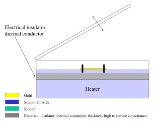
Transverse heat diffusion If the initial temperature distribution within a thermally insulated solid of uniform thickness L is T(x,0), the temperature distribution at any later time t is given by: H. S. Carslaw and J. C. Jaeger, Conduction of Heat in Solids (Oxford University Press, New York, 1959), 2nd ed., p. 101. Can be solved recursively for a=a(T(x,t)), using small time increments heater cable surroundings insulation DQ x L 0 The amount of heat introduced in the “heater” zone at each step is calculated based on the heater resistance R(T(x,t)), heat capacity c(T(x,t)) and current I(t)
Simulation of heater operation U0=100 V C=50 mF Heater (SS304) thickness = 120 micron Heater length = 1 m Heater width = 10 mm Insulation – 140 micron of Kapton 59 ms to reach 18.6 K at ~0.8 mm depth into the “cable”
Heater delay studies Experimental verification of heater performance in and calibration of delay versus heater power, magnet current and ambient temperature was conducted for HQ01 and is in progress for HQ02. These data are of great value for calibrating numerical tools and optimizing heater geometry based on variation of the quench delay values for different sections of the winding. HQ01e % of Iss T. Salmi, H. Felice
Heater temperature evolution in HQ01d 5 % Heater temperature reaches a maximum ~35 ms after HFU firing. This is a long time for protection! Resistance of the four-heater circuit after HFU firing Heater temperature rises to ~90 K This is still a low temperature for preserving the integrity of heater material 5 %
Conclusions • Heater design work is in progress at LBL, involving • development of the simulation tools • verification with current and future magnet tests (HQ, LHQ) • search for the better heater material and doing evaluative studies • new ideas about optimizing heater powering scheme LQ/LHQ style heater pattern is proposed as basis for the QXF heaters; its further optimization will be done using existing and newly developing tools. It is also pending experimental verification of performance in the upcoming LHQ mirror test.