Download
1 / 18
180 likes | 184 Vues
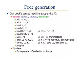
ESMF Code Generation. Rocky Dunlap Spencer Rugaber Leo Mark Georgia Tech College of Computing. Motivation and Goals. Automatically generate Fortran code for coupling Earth System Modeling Framework (ESMF) components, including: A top level driver A coupler component

E N D
ESMF Code Generation Rocky Dunlap Spencer Rugaber Leo Mark Georgia Tech College of Computing
Motivation and Goals • Automatically generate Fortran code for coupling Earth System Modeling Framework (ESMF) components, including: • A top level driver • A coupler component • Determine to what extent coupled Earth System Models* are amenable to code generation • Auto-generation of couplers is part of the original Curator proposal The word model is overloaded. When referring to a computer simulation we will use the term numerical model or coupled model. Otherwise, when used alone, the term model refers to an abstract representation of reality.
Process Overview 1 2 3 Describe existing components based on source code Describe a coupling configuration Generate the source code for a coupler and a driver module comp2 … <comp1> ... </comp1> <comp2> … </comp2> module comp1 … Code Generator <comp1> ... </comp1> <comp2> … </comp2> module coupler … program driver …
Case study: ESMF_ArrayRedistSTest • One-way coupling scenario with two gridded components: user_model1 and user_model2 • user_model1 populates 100x150 global array • user_model2 verifies array data • user_model1 runs on 4 processors (PETs) with a 4x1 DELayout (i.e., four 25x150 local arrays) • user_model2 runs on 2 PETs with a 1x2 DELayout (i.e., two 100x75 local arrays) • System test includes the coupler for redistributing array data and a t0p level driver • Given user_model1 and user_model2, our goal is to generate the coupler and the driver code
Process Overview – Inputs & Outputs • You have: • Fortran source code for two ESMF gridded components • You put in: • A description of those components • A description of a coupling configuration: composition, schedule, and deployment • You get out: • Fortran source code for an ESMF driver and an ESMF coupler component
System Architecture ESMF Code Generation ESMF Coupler Generator JFOM Instances JFOM Instances JFOM Instances ESMF Driver Generator FORTRAN Code Generation ESMF Conceptual Modeling ESMF Configuration Instance ESMF Configuration Instance ESMF Configuration Instances (ECIs) ECM Modeling GUI Java Fortran Object Model (JFOM) ESMF Conceptual Model (ECM) StringTemplate Eclipse Modeling Framework (EMF)
Existing Infrastructure Pieces • Eclipse Modeling Framework • http://www.eclipse.org/emf/ • “…a modeling framework and code generation facility for building tools and other applications based on a structured data model” • Models are built using a UML-like, object-oriented metamodel called Ecore • StringTemplate • http://www.stringtemplate.org/ • a Java-based template engine for generating formatted text output • templates are strings with “holes” that can be populated programmatically and then output
The ESMF Conceptual Model (ECM) • Built with the Eclipse Modeling Framework • A conceptual model of ESMF data structures: • Gridded and Coupler Component, Import/Export State • Virtual Machine, PETs, DELayout • DistGrid, Array • Not included (yet): Field, Grid, Clock, Calendar • Also includes new structures for describing coupling configurations: • Composition – how the components are connected • Schedule – order of execution of components • Deployment – map components to physical resources
ECM Graphical User Interface • The coupled model designer builds ESMF Configuration Instances (ECIs) using a GUI like the one shown here • This current GUI is generated automatically with the Eclipse Modeling Framework
JFOM: Fortran Conceptual Model • ECIs are input to the code generation phase. We need an API for manipulating Fortran programs. • Java Fortran Object Model (JFOM) • built with the Eclipse Modeling Framework • a set of Java classes that represent the syntactic structures of Fortran programs • based on the Fortran 90 grammar • allows programmatic manipulation of Fortran programs • JFOM instances are serialized with StringTemplate
JFOM Classes JFOM classes represent the syntactic structures of Fortran 90
Models and Instances ESMF Conceptual Model (ECM) Java Fortran Object Model (JFOM) FORTRAN 90 ISO Standard Model level conform ESMF Configuration Instance (ECI) JFOM Instance FORTRAN source code Instance level transform transform
Case study: ESMF_ArrayRedistSTest • Given user_model1 and user_model2, our goal is to generate the coupler and the driver code • First step is to build an ECI containing a description of user_model1, user_model2, and the coupling configuration • The ECI is passed to the ESMF Coupler Generator and ESMF Driver Generator resulting in two JFOM instances • The JFOM instances are serialized into Fortran 90 code and can be compiled with user_model1 and user_model2 to recreate the system test
What code is generated? • Driver program (see source code) • Module imports and global variable declarations • ESMF_Initialize • ESMF_GridCompCreate and ESMF_CplCompCreate • ESMF_StateCreate for import/export states • Call Init, Run, Finalize for each component (just once for now) • ESMF_StateDestroy, ESMF_Finalize • Coupler module (see source code) • Module imports and global variable declarations • register, init, run, finalize subroutines • init: ESMF_StateReconcile and ESMF_ArrayRedistStore • run: ESMF_ArrayRedist • finalize: ESMF_ArrayRedistRelease • What is not generated? • source code for user_model1 and user_model2 • makefiles, configuration scripts, etc.
Design Decisions • How much of the ECI (coupling configuration) is described explicitly by the modeler and how much is inferred? • For example, does the user describe component connections at the field level, or should the system infer field connections by matching names? • Tradeoffs: Defining things explicitly gives the modeler more control. Inferring things means the modeler does less work. • Where and when is the inferencing done? • The UI could provide inferencing tools to “fill in” details of the coupling configuration automatically. • There is a notion of a “completely specified” ECI in which the code generator does not do any inferencing. Should we make the assumption that all coupling scenarios coming out of the UI will be complete?
Design Decisions (cont.) • The code generator deals primarily with a model’s communication infrastructure. How do we deal with the science embedded in components? • Do we provide hooks for science? (Can we get to a point where the modeler only has to write the scientific code?) • What about couplers that have embedded science?
Next steps • What is the next step for exercising the code generator? • Other system tests? • Real applications? • In general, what are the realistic applications of code generation for Earth System Models? • What will be the role of reverse engineering of existing model source codes? • How does the approach compare to other frameworks (e.g., BFG2, OASIS)? Can we generate inter-framework couplers? • The ECM and the JFOM are actually distinct technologies. What other uses can we imagine for them?
Thanks! Questions? code generation its Springtime has finally come a happy climate