Download
1 / 85
2.36k likes | 3.92k Vues
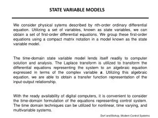
Chapter 10 State Variable Analysis. Automatic Control Systems, 9 th Edition F. Golnaraghi & B. C. Kuo. 1, p. 673. 10-1 Introduction. Objectives of this chapter : Introduce the basic methods of state variables and state equations .

E N D
Chapter 10State Variable Analysis Automatic Control Systems, 9th Edition F. Golnaraghi & B. C. Kuo
1, p. 673 10-1 Introduction Objectives of this chapter: • Introduce the basic methods of state variables and state equations. • Present the closed-form solutions of LTI state equations. • Establish the relationship between the transfer-function approach and the state-variable approach. • Define controllability and observability of linear systems.
2, p. 673 10-2 Block Diagrams, Transfer Functions, and State Diagrams Transfer Functions (Multivariable Systems) • A linear system hasp inputs and q outputs. • Transfer function betweenthe jth input & theith output:Rk(s) = 0, k = 1,2,…,p, k j. • The jth output when all inputs are in action:
2, p. 673 Transfer Func. in Matrix-Vector Form • 10-2-2 Block Diagrams and Transfer Functions of Multivariable Systems See Section 3-1-5 (pp. 117-119)
2, p. 677 State Diagram The basic elements of a state diagram are similar to the SFG, except for the integration operation. • A state diagram can be constructed directly from the system’s differential equations. • A state diagram can be constructed from the system’s transfer function. • The state-transition equation may be obtained from the state diagram by using the SFG gain formula. • The transfer function of a system can be determined from the state diagram. • The state equations and the output equations can be determined from the state diagram.
2, p. 677 SFG Representation of Integration
2, p. 678 From Differential Equations to State Diagram Step 1: arrange the nodes Figure 10-5 (a) Step 2: connect the branches to portray Eq. (10-25) Figure 10-5 (b)
2, p. 678 From Differential Equations to State Diagram Step 3: insert the integrator branches with gains of s1and add the initial conditions to the outputs of the integrators Figure 10-5 (c) The outputs of the integrators are defined as the state variables, x1, x2, …, xn.
2, p. 679 Example 10-2-2
2, p. 680 From State Diagrams to Transfer Func. • Using the gain formula and setting all other inputs and initial states to zero. • Example 10-2-3:
2, p. 680 From State Diagrams to State/Output Eqs. • State equation: • Output equation: • Delete the initial states and the integrator branches. • State equations: regard the nodes that represent the derivatives of the state variables as output nodes.Output equation: the output y(t) in the output equation is an output node variable. • Regard the state variables and the inputs as input variables. • Apply the SFG gain formula to the state diagram.
2, p. 680 Example 10-2-4
2, p. 681 Example 10-2-5
3, p. 682 10-3 Vector-Matrix Representation of State Equations • State equations: • Output equations: • Dynamic equations (LTI systems): • State equations: • Output equations: disturbance vector state vector input vector
4, p. 684 10-4 State-Transition Matrix The state-transition matrix is defined as a matrix thatsatisfies • (t):state-transition matrix • x(0): initial state (10-53) (10-54)
4, p. 685 Properties of State-Transition Matrix (t2t1): the transition of the state from t = t1 to t = t2 when the inputs are zero.
5, p. 687 10-5 State-Transition Equation • State equation: • Output equation:
5, p. 688 Example 10-5-1
5, p. 689 State-Transition Equation Determined from State Diagram (10-89) can be written from the state diagram using the gain formula with Xi(s), i = 1, 2, …, n, as the output nodes. • Example 10-5-2:
5, p. 690 Example 10-5-2 (cont.)
5, p. 690 Example 10-5-3 state equation:
5, p. 691 Example 10-5-3 (cont.) Using the state transition approach: • : • :
6, p. 692 10-6 Relationship between State Equations and High-Order Differential Equations • phase-variable canonical form (PVCF) orcontrollabilitycanonical form (CCF) • State equation: • Output equation:
6, p. 693 Example 10-6-1 state variables state equations: output equation:
7, p. 693 10-7 Relationship between State Equations and Transfer Functions LTI systems: • State equations: • Output equation: • Transfer function: initial condition x(0) = 0
7, p. 694 Example 10-7-1
7, p. 694 Example 10-7-1 (cont.)
7, p. 695 Example 10-7-1 (cont.)
8, p. 695 10-8 Characteristic Equations, Eigenvalues, and Eigenvectors • Characteristic equation: • Transfer function: • State equations: n > m
8, p. 696 Examples 10-8-1 ~ 10-8-3 • From differential equation: • From transfer function: • From state equations:
8, p. 697 Eigenvalues & Eigenvectors • Eigenvalues of A:the roots of the characteristic equation • Eigenvector of A associated with the eigenvalue i:pi: any nonzero vector • Example 10-8-5: State equation with the coefficient matrix • Characteristic equation: • Eigenvalues: • Eigenvectors:
8, p. 698 Generalized Eigenvectors Assume that there are q (<n)distincteigenvalues amongthe n eigenvalues of A. • Eigenvectors corresponded to the q distinct eigenvalues: • Generalized eigenvectors: the eigenvectors corresponded to the remaining high-order eigenvalues. j: the mth order eigenvalue ( m n q)
8, p. 698 Example 10-8-6 • : • : • :
9, p. 699 10-9 Similarity Transformation • P:nonsingular matrix
9, p. 700 Invariance Properties • Characteristic Equations, Eigenvalues & Eigenvectors: • Transfer-Function Matrix:
9, p. 701 Controllability Canonical Form (CCF) • Characteristic equation: • CCF transformation matrix: • CCF model: controllability matrix
9, p. 702 Example 10-9-1 Coefficient matrices: i) Controllability matrix: ii) iv) iii)
9, p. 703 Observability Canonical Form (OCF) • Characteristic equation: • OCF transformation matrix: • OCF model: observability matrix
9, p. 703 Example 10-9-2 Coefficient matrices: i) observability matrix: ii) OCF transformation matrix: iii) OCF model:
9, p. 704 Diagonal Canonical Form (OCF) • Coefficient matrix A has n distinct eigenvalues, 1, 2, …, n. • DCF transformation matrix:pi, i = 1,2,…,n: the eigenvector associated with i. • DCF model:
9, p. 705 OCF and Example 10-9-3 • If A is of CCF and A has distinct eigenvalues, then • Example 10-9-3:
10, p. 707 10-10 Decompositions of Transfer Funcs. Figure 10-13 Block diagram showing the relationshipsamong various methods of describing linear systems.
10, p. 708 Direct Decomposition to CCF • The nth-order SISO system: 1. Express the transfer function in negative powersof s.2. Multiply by a dummy variableX(s).3.4. Construct the state diagram using (10-227) and (10-229).
10, p. 709 CCF State Diagram & Dynamic Eqs. CCF state diagram
10, p. 709 Direct Decomposition to OCF OCF state diagram
10, p. 710 OCF Dynamic Equations
10, p. 710 Example 10-10-1 • CCF dynamic equation: • OCF dynamic equation:
10, p. 711 Example 10-10-1 (cont.)
10, p. 712 Cascade Decomposition • State diagram: • Dynamic equations:
10, p. 712 Cascade Decomposition: Example • State diagram: • Dynamic equations: