Download
1 / 76
1.09k likes | 2.21k Vues
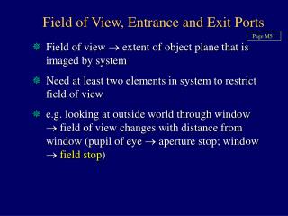
Page M51. Field of View, Entrance and Exit Ports. Field of view extent of object plane that is imaged by system Need at least two elements in system to restrict field of view

E N D
Page M51 Field of View, Entrance and Exit Ports Field of view extent of object plane that is imaged by system Need at least two elements in system to restrict field of view e.g. looking at outside world through window field of view changes with distance from window (pupil of eye aperture stop; window field stop)
Field of View, Entrance and Exit Ports Aperture stop and field stop together limit field of view. Define entrance and exit ports as images of field stop from object and image space Entrance and exit ports (for field stop) analogous to entrance and exit pupils (for aperture stop)
Field Stop If field stop constricted largest angle subtended by rays with axis decreases
Defining Field of View Referred to object space actual field of view Actual FOV uses entrance pupil and entrance port Referred to image space apparent field of view Apparent FOV uses exit pupil and exit portWe typically define FOV in terms of semi-angles with the optical axis
Apart from defining real (object space) and apparent (image space) FOV also define FOV in terms of rays admitted to system: Field of View Full Field (Field of Maximum Illumination) Half Field (Field of Half Illumination) Total Field of View (Extreme Field)
Most restrictive definition of FOV.Full field corresponds to optimum image quality and uniformity of illumination. Full Field (Field of Maximum Illumination) Define as: Portion of object field giving no appreciable drop in image illumination compared with the “axial” value Quantitative: angle subtended by the cone of rays admitted through both entrance port and entrance pupil
Full Field (Maximum Illumination) (½) cone of rays admitted through entrance port and entrance pupil Full Field Page M52
Full Field (Maximum Illumination) Full Field This represents the totally unrestricted (non-vignetted) cone of rays traveling through the system Page M52 For all locations in the object field, 100% of the rays are transmitted into image space Angle of obliquity is least and reflection losses lowest for this incident cone of rays
Most common definition of FOV.When the term “field of view” is used without qualification implies half field Page M52 Half Field (Field of Half Illumination) Define as: Portion of object field giving rise to image illuminance of at least half the axial value Quantitative: angle subtended by radius of entrance port at center of entrance pupil
Vignetting Half Field (at Least Half Illumination) Vignetting Half Field Page M52
Page M52 This encompasses all of the rays that can get through the system, including the most oblique admitted rays these form the dimmest parts of the image margin Total Field (Extreme Field) Define as: Entire bundle of rays that can participate in image formation Quantitative: angle subtended by one edge of the entrance pupil at the opposite edge of the entrance port
Vignetting Total Field of View Vignetting Extreme Field Page M52
Field of View Vignetting Page M52 Total Field of View Full Field (Maximum Illumination) Half Field (at Least Half Illumination) Vignetting
Example 12 Page M53 • A +20 D lens (3 cm diameter) is placed 3 cm in front of an iris diaphragm (1 cm diameter) • An axial object is located 100 cm (1 meter) in front of the lens • Find: • The aperture stop • Field of view, expressed as: • Field of full illumination (full field) • Field of half illumination (half field) • Total field of view (extreme field)
Example 12 • Find: • The aperture stop Page M53 • Candidates: +20 D lens; iris diaphragm
Example 12 Page M53 • Lens: if the lens is the aperture stop, it is also the entrance pupil (no preceding optical components) • EnP 3 cm diameter, 100 cm from axial object point
Iris Diaphragm Example 12 Page M53 SYSTEM NOT REVERSED
EnP Candidates Example 12 Page M53 A • The iris diaphragm is the aperture stop • The +20 D lens is the field stop (and entrance port, since no optical components precede it)
Example 12 Page M53 • A +20 D lens (3 cm diameter) is placed 3 cm in front of an iris diaphragm (1 cm diameter) • An axial object is located 100 cm (1 meter) in front of the lens • Find: • The aperture stop • Field of view, expressed as: • Field of full illumination (full field)
Field of Full Illumination Page M54 Angle subtended by the radius of the En Port at the “radius” of the En Pupil NOT TO SCALE
Field of Full Illumination Page M55 Full field corresponds to twice 1 = 3.82O
Example 12 Page M55 • A +20 D lens (3 cm diameter) is placed 3 cm in front of an iris diaphragm (1 cm diameter) • An axial object is located 100 cm (1 meter) in front of the lens • Find: • The aperture stop • Field of view, expressed as: • Field of full illumination (full field) • Field of half illumination (half field)
Field of Half Illumination Page M55 Angle subtended by the radius of the En Port at the center of the En Pupil NOT TO SCALE
Field of Half Illumination Page M55 Half field corresponds to twice = 22.6O
Example 12 Page M56 • A +20 D lens (3 cm diameter) is placed 3 cm in front of an iris diaphragm (1 cm diameter) • An axial object is located 100 cm (1 meter) in front of the lens • Find: • The aperture stop • Field of view, expressed as: • Field of full illumination (full field) • Field of half illumination (half field) • Total field of view (extreme field)
Total Field View Page M56 Angle subtended by the margin of the En Port at the opposite margin of the En Pupil NOT TO SCALE
Page M56 Total Field View Check notes p. M56 Total field corresponds to twice 2 = 40.3O
Uniformity of Illumination NOT TO SCALE
Page M57 Entrance and Exit Pupils in Telescopes
Larger than objective;for distant object cannot be entrance pupil EnP and ExP in Astronomical Telescope e.g. FO = +10 D (10 cm diameter); FE = +40 D (4 cm diameter) image of eyepiece 16 cm diameter
Exit Pupil in Astronomical Telescope • Eye Relief - Distance between Eyepiece and ExP • Exit pupil is real observer can place their eye at ExP • Maximum FOV with observer’s EnP at telescope ExP • Optimum image quality when observer’s EnP diameter matches telescope ExP diameter
EnP and ExP in Astronomical Telescope Afocal setting ExP diameter matches diameter of circle of light
EnP and ExP in Astronomical Telescope Can “capture” ExP on screen measure ExP diameter (D)
Finding Magnification from EnP:ExP Diameter • Measure objective (EnP) diameter (D) • Point telescope at daytime skyImage ExP on screen to measure D • Ratio D/D gives telescope angular magnification (M)
Chief Ray Enhances image quality & uniformity of illumination Ray Bundle through Astronomical Telescope
Virtual Exit Pupil Galilean Telescope Page M59
Field of View in Galilean Telescope • Virtual exit pupil cannot place observer’s EnP at telescope ExP • Potential FOV therefore greatly reduced • Uniformity of image illumination compromised because a field stop cannot be placed at the (virtual) common focus
Page M61 Calculating Field of View
Calculating Field of View Start simple: Simple (Positive Lens) Magnifier
Simple Magnifier - Half Field (Field of Half Illumination) • Portion of object field giving rise to image illuminance of at least half the axial value • Angle subtended by radius of entrance port at center of entrance pupil
Simple Magnifier - Field of View • Pupil of eye limits light entry from magnifier system aperture stop (also ExP, if reduced eye) • System EnP image of pupil through magnifier • Magnifier = Field Stop (no other apertures)
Page M62 Calculating Field of View Return to compound case: Astronomical Telescope
Field of View - Astronomical Telescope • Field of half illumination depends on diameter of field stop (a) at second focus of objective (FO ) • Primary image also at FO both field stop and primary image focused in same plane () by FE • This creates an image with a sharply defined edge
to (to EnPort) Field of View - Astronomical Telescope • Image of field stop through FO at - EnPort • angle subtended by radius of EnPort at center of En Pupil is (or can “follow” out to - to EnPort) • defines field of half illumination when ExP diameter matched to (blue shaded) field stop bundle
to (to EnPort) Not matched: field stop too large Field of View - Astronomical Telescope Eyepiece may become field stop • defines field of half illumination when ExP diameter matched to (blue shaded) field stop bundle