Download
1 / 29
351 likes | 489 Vues
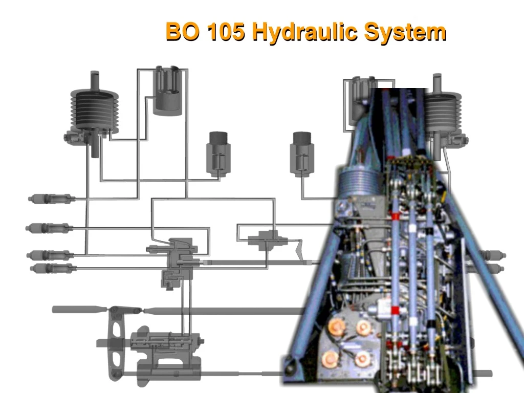
BO 105 Hydraulic System. LOCATION OF HYDRAULIC BOOSTER UNIT. Located on the right side of the fuselage under an access panel. The unit is completely self contained with the only hoses being from the transmissions mounted twin pumps. BO 105 Hydraulic System Overview.

E N D
LOCATION OF HYDRAULIC BOOSTER UNIT Located on the right side of the fuselage under an access panel. The unit is completely self contained with the only hoses being from the transmissions mounted twin pumps
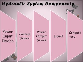
BO 105 Hydraulic SystemOverview • Located on left side of fuselage. • Boosts manual control inputs. • Two systems for redundancy. • Hydraulic pack can be removed without removal of hydraulic line or hose fittings. • Has external couplings for GPU or manually operated hydraulic unit. Boosted Output Manual Input
HYDRAULIC SYSTEM Fluid Reservoirs Low pressure filter indicators High pressure filter indicators Micro-switches Shuttle valve Control Inputs System 1 (Primary) System 2 (Back-up)
BO 105 CBS SystemConcept of the Parallelogram Hydraulic System Points C and D represent the points that you can influence with your control inputs D C E F A B Points A and B represent the points controlled by the dual boost cylinders Points F and E represent the pivot points about which AB and CD move. These points sit on the control sliders for both boost cylinders. They can move the control sliders slightly right and left to accommodate selection of the path for the high pressure fluid which will control the boost pistons. To sum this, you move CD, and therefore move EF. This movement of EF hydraulically controls the opposite movement of AB to influence of the rotor system.
LOCATION OF HYDRAULIC TEST SWITCH TWO POSITION SWITCH: HYDR RESET
BO 105 CBS SystemPressure Switch Location Electrical Connection Hi Pressure Inlet System 1 Pressure Switch System 2 Pressure Switch
BO 105 CBS SystemReservoirs and Low Pressure Filters • System 1 Reservoir (Sys 2 identical) • Reservoir Housing • Quantity Indicator • Filter Pop-out Button • Uses high pressure from the pump to maintain a positive pressure on the fluid
BO 105 CBS SystemReservoirs and Low Pressure Filters • Reservoir contains two pistons: • Low Pressure • High Pressure • Fluid waiting in the Reservoir is pressurized by the Low pressure piston. • High pressure fluid from the pump forces the low pressure piston to compress the reservoir. TO PUMP
BO 105 CBS SystemTwin Hydraulic Pumps • Two separate pumps driven at the transmission • Provide contant pressure • Variable Volume • Each pump contains four lines: • Feed line-from the reservoir to the pump • Output line-high pressure to the system • Case drain line-fluid is allowed to pass around the pistons and is used to lubricate and cool the pump • Seal drain line-allows any high pressure leakage at the input shaft to escape overboard and prevent gearbox contamination. (not displayed in diagram)
ROTATION ROTATION ROTATION BO 105 CBS SystemPump Schematic • Piston assembly is turned by the transmission • Bottom of each piston is fixed with a ball joint • The backplate is fixed to the piston assembly but can vary its angle to deliver a variable volume at the same pressure • As the pistons turn and descend, they draw in fluid from the reservoir • The pistons pass the cutoff plate where the fluid becomes trapped • The pistons then rise, pushing the fluid into the outlet and into the system under pressure.
BO 105 CBS SystemSolenoid Valve Spring Port to the Shuttle Valve High Pressure Port Return Port (to the low pressure side) Control Piston EMERGENCY OPERATIONS Electro Magnet Active High pressure is routed to the low pressure side NORMAL OPERATIONS Electro Magnet standby Electro Magnet
BO 105 CBS SystemShuttle Valve Shuttle valve-valve assembly Surface area for System 1 is greater than the Surface area for System 2 Connected to a bell crank attached to the Selector Valve Selector Valve Operates in both valve blocks Controlled by the position of the Shuttle Valve thru the bell crank Normally allows hydraulic power from System 1 to power the flight controls If System 1 is active, System 2 will be closed.
BO 105 CBS SystemShuttle Valve HYD 1 System 1 has more surface area on the valve than System 2 and will force the valve to the right selecting System 1 to provide hydraulic power. If System 1 pressure fails, System 2 pressure will force the valve to move left and open the valve in #2 Valve Block allowing System 2 to provide hydraulic pressure to the aircraft
BO 105 CBS SystemValve Block Valve Block Components Test Screw – allows main pressure to pass around the regulator and the check valve for testing purposes. Limiting Valve (pressure regulator) – Adjustable spring loaded valve used to allow excess pressure to bleed into the low pressure side as a safety precaution should a high pressure condition exist. Check Valve – Spring loaded ball type used to prevent extreme pressure loads caused by rotor loading on the boost cylinder from back feeding to the pumps. Selector Valve – controlled by the shuttle to switch hydraulic power from System 1 to System 2. High Pressure Filter – Cleans the hydraulic fluid passing to the boost cylinder. High Pressure Filter Bypass Indicator assembly – In the event of a filter clog, differential pressure will force the assembly to push down and pop out the red clog indicator. High Pressure Filter Bypass – In the event of a total filter clog, the bypass will open and allow pressure to continue to the boost cylinder.
BO 105 CBS System BO 105 CBS SystemValve Block P E Valve Block Operation In the event that the filter should partially clog, pressure on the front and back side of the filter will be different. This differential pressure will cause the clogging indicator to extend During normal operation with the Filter unclogged, high pressure fluid passes through on its way to the boost cylinder. PE (High Pressure in from pump) – high pressure enters the valve block and moves to the check valve and limiting valve Return (Low Pressure) from the boost cylinder travels up through the valve block on its way back to the reservoir. This path also provides a way for the Limiting valve to dump excess pressure back into the low pressure side. R (to the reservoir) The check valve opens and allows the high pressure enters the shuttle valve orifice and on to the high pressure filter. Additional fluid travels around the filter to the bypass valve and the indicator pin assembly. In this condition, pressure is equal on both sides of the assembly. The indicator will not extend nor the bypass open In the event that the filter should completely clog, pressure on the back side of the filter will be unusable. Should this happen, the bypass will open and allow pressure to travel into the boost cylinder to prevent a loss of hydraulic power. The limiting valve stays closed since it only opens when pressure is greater than normal. R P
BO 105 CBS System BO 105 CBS SystemValve Block Check Valve and Limiting Valve P E Valve Block Operation In the event of higher than normal pressure on the high pressure side, the Limiting valve will open all allow excess pressure to bleed over into the low pressure side. This prevents excessive pressure from damaging other components down stream. Regulated pressure still travels down stream, but all excess pressure is bled into the low pressure system. In the event of high rotor loads sending a high pressure surge back through the high pressure system, the check valve will close and block the surge from traveling back through the system. R (to the reservoir) R P
BO 105 CBS System BO 105 CBS SystemBoost Cylinder
BO 105 CBS System BO 105 CBS SystemBoost Cylinder Components Boost Cylinder Components High Pressure – Enters the boost cylinder after passing through the valve block. Used to move the boost piston and hold the bypass pistons in position. Actuator Housing – two of these assemblies are mounted opposing each other Boost Piston – directly connected to the boost piston on the opposing cylinder, this piston uses high pressure hydraulic fluid to overcome aerodynamic forces to control your inputs into the main rotor Low Pressure – After being used to produce work on the main rotor, low pressure fluid provides a dynamic seal on the boost piston, then travels through the valve block on its way to the reservoir. Bypass Pistons – Normally held closed with high pressure fluid, these pistons allow fluid trapped in the boost cylinder during a hydraulic failure to pass freely from one chamber to another. Control Slider – based on its position, it controls the flow of high and low pressure fluid to the boost piston.
BO 105 CBS System BO 105 CBS SystemBoost Cylinder Operation Boost Cylinder Operation When you make a flight control input, you first move the control slider. This opens a port to direct the fluid to travel to the boost piston and and away from the boost piston back to the reservoir. Moving the flight controls in the opposite direction produces the same result. The boost piston moves the opposite direction. When you stop moving the flight controls, the boost piston will continue to move until it closes the control slider and returns the fluid to a non-moving state. The boost piston moves opposite the control slider and continues to move until you stop making a input. The boost piston continues to move until its movement closes the control slider and returns the fluid to a non-moving state inside the cylinder. Fluid at rest and becomes dynamic after start. Normal Operations
BO 105 CBS SystemBoost Cylinder Operation Boost Cylinder Bypass Mode Without such a system, damage could occur to System 1 components as trapped fluid would be forced back against the control slider which would damage the boost piston. To remedy this problem, these bypass pistons have been incorporated. Should a HYD System 1 failure occur, System 2 will be providing pressure to the system. In this event, there must be a way for the boost cylinder to allow fluid to travel freely between both sides of the boost piston. As discussed earlier, these bypass pistons are held in position by high pressure fluid from the pump. When that disappears in a hydraulic failure, nothing will hold them in position. Back pressure caused by the movement of the boost piston will open the bypass pistons. This provides a short and easy path for the trapped fluid to travel and prevent dangerous back pressure from traveling up through the system.
BO 105 CBS SystemNormal Operations HYD 2 HYD 1 HYD 1 (Primary) HYD 2 (Secondary)
BO 105 CBS System BO 105 CBS SystemSystem 1 Pressure Failure HYD 2 HYD 1
BO 105 CBS SystemSolenoid Valve Activation (System 1) HYD BLOCK HYD 2 HYD 1
BO 105 CBS SystemSystem 2 Pressure Failure HYD 2 HYD 1