Download
1 / 27
2.2k likes | 6.18k Vues
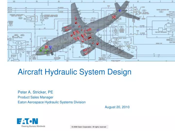
Aircraft Hydraulic System Design. Peter A. Stricker, PE Product Sales Manager Eaton Aerospace Hydraulic Systems Division August 20, 2010. Purpose. Acquaint participants with hydraulic system design principles for civil aircraft

E N D
Aircraft Hydraulic System Design Peter A. Stricker, PE Product Sales Manager Eaton Aerospace Hydraulic Systems Division August 20, 2010
Purpose • Acquaint participants with hydraulic system design principles for civil aircraft • Review examples of hydraulic system architectures on common aircraft
Agenda • Introduction • Review of Aircraft Motion Controls • Uses for and sources of hydraulic power • Key hydraulic system design drivers • Safety standards for system design • Hydraulic design philosophies for conventional, “more electric” and “all electric” architectures • Hydraulic System Interfaces • Sample aircraft hydraulic system block diagrams • Conclusions
Introduction Hydraulic power is generated mechanically, electrically and pneumatically 5 Air Turbine Pump Hydraulic system transmits and controls power from engine to flight control actuators 2 Hydraulic Storage/Conditioning Electric Motorpump Ram Air Turbine Pump Pilot Inputs Electric Generator Flight Control Actuators Engine Pump Pilot commands move actuators with little effort 4 As airplanes grow in size, so do the forces needed to move the flight controls … thus the need to transmit larger amount of power 1 Pilot inputs are transmitted to remote actuators and amplified 3
Introduction • Aircraft’s Maximum Take-Off Weight (MTOW) drives aerodynamic forces that drive control surface size and loading • A380 – 1.25 million lb MTOW – extensive use of hydraulics • Cessna 172 – 2500 lb MTOW – no hydraulics – all manual
Controlling Aircraft MotionPrimary Flight Controls Definition of Airplane Axes 1 3 2 1 Ailerons control roll 2 Elevators control pitch 3 Rudder controls yaw
Controlling Aircraft MotionSecondary Flight Controls • High Lift Devices: ► • Flaps (Trailing Edge), slats (LE Flaps) increase area and camber of wing • permit low speed flight • Flight Spoilers / Speed Brakes: permit steeper descent and augment ailerons at low speed when deployed on only one wing • Ground Spoilers: Enhance deceleration on ground (not deployed in flight) • Trim Controls: • Stabilizer (pitch), roll and rudder (yaw) trim to balance controls for desired flight condition
Example of Flight Controls (A320) PRIMARY SECONDARY REF: A320 FLIGHT CREW OPERATING MANUAL CHAPTER 1.27 - FLIGHT CONTROLS
Why use Hydraulics? • Effective and efficient method of power amplification • Small control effort results in a large power output • Precise control of load rate, position and magnitude • Infinitely variable rotary or linear motion control • Adjustable limits / reversible direction / fast response • Ability to handle multiple loads simultaneously • Independently in parallel or sequenced in series • Smooth, vibration free power output • Little impact from load variation • Hydraulic fluid transmission medium • Removes heat generated by internal losses • Serves as lubricant to increase component life
Typical Users of Hydraulic Power HYDR. MOTOR GEARBOX TORQUE TUBE • Landing gear • Extension, retraction, locking, steering, braking • Primary flight controls • Rudder, elevator, aileron, active (multi-function) spoiler • Secondary flight controls • high lift (flap / slat), horizontal stabilizer, spoiler, thrust reverser • Utility systems • Cargo handling, doors, ramps, emergency electrical power generation Landing Gear Spoiler Actuator Flap Drive Nosewheel Steering
Sources of Hydraulic Power • Mechanical • Engine Driven Pump (EDP) - primary hydraulic power source, mounted directly to engines on special gearbox pads • Power Transfer Unit – mechanically transfers hydraulicpower between systems • Electrical • Pump attached to electric motors, either AC or DC • Generally used as backup or as auxiliary power • Electric driven powerpack used for powering actuation zones • Used for ground check-out or actuating doors whenengines are not running Pneumatic • Bleed Air turbine driven pump used for backup power • Ram Air Turbine driven pump deployed when all engines are inoperative and uses ram air to drive the pump • Accumulator provides high transient power by releasing stored energy, also used for emergency and parking brake Ram Air Turbine Engine Driven Pump Maintenance-free Accumulator AC Electric Motorpump Power Transfer Unit
Key Hydraulic System Design Drivers • High Level certification requirement per aviation regulations: Maintain control of the aircraft under all normal and anticipated failure conditions • Many system architectures* and design approaches exist to meet this high level requirement – aircraft designer has to certify to airworthiness regulators by analysis and test that his solution meets requirements • Hydraulic System Architecture: Arrangement and interconnection of hydraulic power sources and consumers in a manner that meets requirements for controllability of aircraft
Redundancy in case of failures must be designed into system Any and every component will fail during life of aircraft Manual control system requires less redundancyFly-by-wire (FBW) requires more redundancy Level of redundancy necessary evaluated per methodology described in ARP4761 Safety Assessment Tools Failure Modes, Effects and Criticality Analysis – computes failure rates and failure criticalities of individual components and systems by considering all failure modes Fault Tree Analysis – computes failure rates and probabilities of various combinations of failure modes Markov Analysis – computes failure rates and criticality of various chains of events Common Cause Analysis – evaluates failures that can impact multiple components and systems Principal failure modes considered Single system or component failure Multiple system or component failures occurring simultaneously Dormant failures of components or subsystems that only operate in emergencies Common mode failures – single failures that can impact multiple systems Examples of failure cases to be considered One engine shuts down during take-off – need to retract landing gear rapidly Engine rotor bursts – damage to and loss of multiple hydraulic systems Rejected take-off – deploy thrust reversers, spoilers and brakes rapidly All engines fail in flight – need to land safely without main hydraulic and electric power sources Considerations for Hydraulic System Designto meet System Safety Requirements
Civil Aircraft System Safety Standards(Applies to all aircraft systems) Examples Minor: Single hydraulic system fails Major: Two (out of 3) hydraulic systems fail Hazardous: All hydraulic sources fail, except RAT or APU (US1549 Hudson River A320 – 2009) Catastrophic: All hydraulic systems fail (UA232 DC-10 Sioux City – 1989)
Multiple independent centralized power systems Each engine drives dedicated pump(s), augmented by independently powered pumps – electric, pneumatic No fluid transfer between systems to maintain integrity System segregation Route lines and locate components far apart to prevent single rotor or tire burst from impacting multiple systems Multiple control channels for critical functions Each flight control needs multiple independent actuators or control surfaces Fail-safe failure modes – e.g., landing gear can extend by gravity and be locked down mechanically System Design PhilosophyConventional Central System Architecture EMP EMP EMP ADP EDP EDP RAT LEFT ENG. SYSTEM 1 SYSTEM 3 RIGHT ENG. SYSTEM 2 ROLL 3 ROLL 2 ROLL 1 PITCH 3 PITCH 2 PITCH 1 YAW 3 YAW 2 YAW 1 LNDG GR OTHERS OTHERS EMRG BRK NORM BRK NSWL STRG OTHERS PTU EDP Engine Driven Pump EMP Electric Motor Pump ADP Air Driven Pump PTU Power Transfer Unit RAT Ram Air Turbine Engine Bleed Air
Two independent centralized power systems + Zonal & Dedicated Actuators Each engine drives dedicated pump(s), augmented by independently powered pumps – electric, pneumatic No fluid transfer between systems to maintain integrity System segregation Route lines and locate components far apart to prevent single rotor or tire burst to impact multiple systems Third System replaced by one or more local and dedicated electric systems Tail zonal system for pitch, yaw Aileron actuators for roll Electric driven hydraulic powerpack for emergency landing gear and brake Examples: Airbus A380, Boeing 787 System Design PhilosophyMore Electric Architecture GEN1 GEN2 EMP EMP EDP EDP RAT LEFT ENG. SYSTEM 1 ELECTRICAL ACTUATORS RIGHT ENG. SYSTEM 2 ROLL 1 ROLL 3 ROLL 2 PITCH 1 ZONAL PITCH 3 YAW 3 PITCH 2 YAW 1 YAW 2 OTHERS OTHERS OTHERS LNDG GR EMRG BRK NW STRG NORM BRK LG / BRK EMERG POWER EDP Engine Driven Pump EMP Electric Motor Pump GEN Electric Generator RAT Ram Air Turbine Generator Electric Channel
System Design PhilosophyAll Electric Architecture “Holy Grail” of aircraft power distribution …. • Relies on future engine-core mounted electric generators capable of high power / high power density generation, running at engine speed – typically 40,000 rpm • Electric power will replace all hydraulic and pneumatic power for all flight controls, environmental controls, de-icing, etc. • Flight control actuators will like remain hydraulic, using Electro-Hydrostatic Actuators (EHA) or local hydraulic systems, consisting of • Miniature, electrically driven, integrated hydraulic power generation system • Hydraulic actuator controlled by electrical input
Fly-by-Wire Pilot input read by computers Computer provides input to electrohydraulic flight control actuator Control laws include Enhanced logic to automate many functions Artificial damping and stability Flight Envelope Protection to prevent airframe from exceeding structural limits Multiple computers and actuators provide sufficient redundancy – no manual reversion Conventional Mechanical Pilot input mechanically connected to flight control hydraulic servo-actuator by cables, linkages, bellcranks, etc. Servo-actuator follows pilot command with high force output Autopilot input mechanically summed Manual reversion in case of loss of hydraulics or autopilot malfunction Fly-by-Wire (FBW) Systems PILOT INPUTS RIGHT WING AUTOPILOT INPUTS LEFT WING BOEING 757 AILERON SYSTEM
Principal System InterfacesDesign Considerations Electrical System Flight Controls Flow under normal and all emergency conditions – priority flow when LG, flaps are also demanding flow Electric motors, Solenoids Power on Demand Electrical power variations under normal and all emergency conditions (MIL-STD-704) Power on Demand Hydraulic power from EDP Avionics Landing Gear Nacelle / Engine Signals from pressure, temperature, fluid quantity sensors Signal to solenoids, electric motors Flow under normal and all emergency conditions – retract / extend / steer Pad speed as a function of flight regime – idle to take-off Hydraulic System
Aircraft Hydraulic ArchitecturesComparative Aircraft Weights Increasing Hydraulic System Complexity
Aircraft Hydraulic ArchitecturesExample Block Diagrams – Learjet 40/45 Mid-Size Jet • MTOW:21,750 lb • Flight Controls: Manual • Key Features • One main system fed by 2 EDP’s • Emergency system fed by DC electric pump • Common partitioned reservoir (air/oil) • Selector valve allows flaps, landing gear, nosewheel steering to operate from main or emergency system • All primary flight controls are manual • Safety / Redundancy • Engine-out take-off: One EDP has sufficient power to retract gear • All Power-out: Manual flight controls; LG extends by gravity with electric pump assist; emergency flap extends by electric pump; Emergency brake energy stored in accumulator for safe stopping EMERGENCY SYSTEM MAIN SYSTEM REF.: AIR5005A (SAE)
MTOW:39,500 lb Flight Controls:Hydraulic with manual reversion exc. Rudder, which is Fly-by-Wire (FBW) Key Features Two independent systems Bi-directional PTU to transfer power between systems without transferring fluid Electrically powered hydraulic power-pack for Emergency Rudder System (ERS) Safety / Redundancy All primary flight controls 2-channel; rudder has additional backup powerpack; others manual reversion Engine-out take-off: PTU transfers power from system #1 to #2 to retract LG Rotorburst: Emergency Rudder System is located outside burst area All Power-out: ERS runs off battery; others manual; LG extends by gravity Aircraft Hydraulic ArchitecturesExample Block Diagrams – Hawker 4000 Super Mid Size REF.: EATON C5-38A 04/2003
MTOW (A321):206,000 lb Flight Controls:HydraulicFBW Key Features 3 independent systems 2 main systems with EDP 1 main system also includes backup EMP & hand pump for cargo door3rd system has EMP and RAT pump Bi-directional PTU to transfer power between primary systems without transferring fluid Safety / Redundancy All primary flight controls have 3 independent channels Engine-out take-off: PTU transfers power from Y to G system to retract LG Rotorburst: Three systems sufficiently segregated All Power-out: RAT pump powers Blue; LG extends by gravity Aircraft Hydraulic ArchitecturesExample Block Diagrams – Airbus A320/321 Single-Aisle REF.: AIR5005 (SAE)
MTOW (B777-300ER): 660,000 lb Flight Controls: Hydraulic FBW Key Features 3 independent systems 2 main systems with EDP + EMP each 3rd system with 2 EMPs, 2 engine bleed air-driven (engine bleed air) pumps, + RAT pump Safety / Redundancy All primary flight controls have 3 independent channels Engine-out take-off: One air driven pump and EMP available in system 3 to retract LG Rotorburst: Three systems sufficiently segregated All Power-out: RAT pump powers center system; LG extends by gravity Aircraft Hydraulic ArchitecturesExample Block Diagrams – Boeing 777 Wide Body CENTER SYSTEM RIGHT SYSTEM LEFT SYSTEM REF.: AIR5005 (SAE)
MTOW:1,250,000 lb Flight Controls:FBW (2H + 1E channel) Key Features / Redundancies Two independent hydraulic systems+ one electric system (backup) Primary hydraulic power supplied by 4 EDP’s per system All primary flight controls have 3 channels – 2 hydraulic + 1 electric 4 engines provide sufficient redundancy for engine-out cases Aircraft Hydraulic ArchitecturesExample Block Diagrams – Airbus A380 Wide Body REF.: EATON C5-37A 06/2006
Conclusions • Aircraft hydraulic systems are designed for high levels of safety using multiple levels of redundancy • Fly-by-wire systems require higher levels of redundancy than manual systems to maintain same levels of safety • System complexity increases with aircraft weight
Federal Aviation Regulations FAR Part 25: Airworthiness Standards for Transport Category Airplanes FAR Part 23: Airworthiness Standards for Normal, Utility, Acrobatic, and Commuter Category Airplanes FAR Part 21: Certification Procedures For Products And Parts AC 25.1309-1A System Design and Analysis Advisory Circular, 1998 Aerospace Recommended Practices (SAE) ARP4761: Guidelines and Methods for Conducting the Safety Assessment Process on Civil Airborne Systems and Equipment ARP 4754: Certification Considerations for Highly-Integrated or Complex Aircraft Systems Aerospace Information Reports (SAE) AIR5005: Aerospace - Commercial Aircraft Hydraulic Systems Radio Technical Committee Association (RTCA) DO-178: Software Considerations in Airborne Systems and Equipment Certification (incl. Errata Issued 3-26-99) DO-254: Design Assurance Guidance For Airborne Electronic Hardware Text Moir & Seabridge: Aircraft Systems – Mechanical, Electrical and Avionics Subsystems Integration 3rd Edition, Wiley 2008 Suggested References