Download

1 / 14
140 likes | 216 Vues
MICE Target Review. Chris Booth Sheffield 12 th June 2006. Overview. Mechanical Support Heavy frame, precisely located on floor gives location w.r.t. beam pipe Carries support for target mechanism EM Drive Unit Stator body containing series of coils Ceramic liner (vacuum seal)

E N D
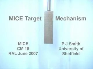
MICE Target Review Chris Booth Sheffield 12th June 2006
Overview • Mechanical Support • Heavy frame, precisely located on floor • gives location w.r.t. beam pipe • Carries support for target mechanism • EM Drive Unit • Stator body containing series of coils • Ceramic liner (vacuum seal) • Ceramic bearings • Optical readout windows (complete vacuum system) • Shuttle: magnets, shaft, target, readout vane, ... • Isolation System • Jacking mechanism • Bellows (200 mm travel) • Gate valve • Electronics to Drive Target • Optical position readout • Electronic control & commutator system • Hex bridge high current drive(s) University of Sheffield
Drive Details • Stator • 24 coils in triplets, driven 3-phase • Water cooling system – copper pipes • Epoxy potting (thermal path) • Thermocouples between coils • Steel end plates • Aluminium cylinder case • Ceramic vacuum liner University of Sheffield
Shuttle • 3 radial magnets (“surf” EM travelling wave provided by coils) • Cross-shaped (or square?) titanium shaft (in cross-shaped (square) bearing aperture) maintains alignment • 11030 mm3 Ti target (radiates beam heating) University of Sheffield
Shuttle (continued) • Stop (to prevent shuttle dropping) • Optical readout vane (interrupts 3 laser beams) University of Sheffield
Isolation System • Jacking mechanism • Raises target’s lowest position well above beam • Stepping motor + position transducer • Hand crank if motor failed • Limit switches, for interlock • Bellows to allow movement, maintaining vacuum • Gate valve • closes to isolate target volume from ISIS vacuum University of Sheffield
Position Readout • 3 remote lasers in control area → optical fibres • Fibre → optical alignment system around windows & position sensing vane • Collimator & lens give focused spot at vane • Vane: comb of 0.3 mm wide teeth (pitch 0.6 mm) • Transmitted beam → lens →collimator → return fibre → optical sensor (control area) • 2 beams in quadrature • direction of movement • resolution = pitch÷4 = 0.15 mm • 3rd beam interrupted by single tooth (other side of vane • absolute position University of Sheffield
Control & Drive System (details in PJS CM talk) • 4 modes • Park → Hold • Actuate enable • Actuate • Hold → Park • Park → Hold & Hold → Park • Do not rely on position sensing • Slow • Low current (~3 A) • Actuate enable • Interlocked with ISIS University of Sheffield
Control & Drive System (2) • Actuate – triggered by ISIS Machine Start • High current (? 80 A) – accelerates target down • Phase controlled by position sensing • ½ way down, current (force) reversed • Decelerates to maximum depth; accelerates up • ½ way up, current reversed again • Decelerates to Hold position • Switches to Hold mode • Power electronics • Trickle charged capacitor bank power supply • Hex bridge (bidirectional switches) • High-current enhancements being developed by Daresbury Power Electronics group University of Sheffield
Interlocks • Gate Valve & Jacking Motor • Target must not damage gate valve diaphragm • Can only operate valve when jack is at upper limit • Can only lower jack when valve is open • Target Drive • Only enter “actuate enable” when ISIS enable present • Only actuate when stator temperature normal • Allow “actuate enable” without “ISIS enable” only at jack upper limit (Debug or test mode) University of Sheffield
Operational Procedure • Target drive installation with gate valve closed, jacking mechanism raised. • Pump down • Open gate valve • Energise coils to raise target to Hold • Lower jack to bottom (operational) position • Enable drive for triggers When MICE is not operational: • Use jack to raise drive mechanism • Park & power off target drive • Close gate valve University of Sheffield
Fault Conditions Over-temperature • inhibit insertion. Failure of target control or drive • Target falls into beam. • Major beam loss each cycle. ISIS trips after 3 pulses. • Jacking mechanism used to raise target clear of beam. Vacuum leak in target drive • Jack raises target. Gate valve closed. University of Sheffield
Current Status • Maximum drive current 10 A • Stroke 39 mm in 60 ms • Repetition Rate ~3 Hz • Peak Acceleration 15-20 g Requirements • Maximum drive current 80 A (?) • Stroke 24 mm in 20 ms • Repetition Rate ≥1 Hz • Peak Acceleration ~100 g University of Sheffield
Open Questions • Details of titanium shaft – Oxford workshop • Type of ceramic metal seal – Indium/bonded • Details of optical windows – RAL/Sheffield design • Adequacy of stator cooling – modified cooling to be tested (effect of eddy currents?); no. of coil banks • Radiation damage to magnets • Radiation damage to magnet glue? • Radiation damage to optical components (fibre, collimator, lens) • Replaceable drive units, designed for rapid exchange • Margin for increased laser power, increased current? • Beam or electrical noise in thermocouples/cables • Alternative devices? University of Sheffield