Download
1 / 34
350 likes | 593 Vues
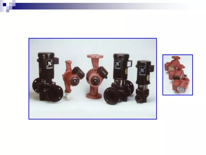
Pump Basics. Centrifugal Pumps. A machine for moving fluid by accelerating the fluid RADIALLY outward. From the Center of a Circle. RADIAL DIRECTION To the Outside of a Circle. Centrifugal Pumps. This machine consists of an IMPELLER rotating within a case (diffuser)

E N D
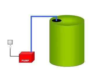
Centrifugal Pumps A machine for moving fluid by accelerating the fluid RADIALLY outward. From the Center of a Circle RADIAL DIRECTION To the Outside of a Circle
Centrifugal Pumps • This machine consists of an IMPELLER rotating within a case (diffuser) • Liquid directed into the center of the rotating impeller is picked up by the impeller’s vanes and accelerated to a higher velocity by the rotation of the impeller and discharged by centrifugal force into the case (diffuser).
Centrifugal Pumps • A collection chamber in the casing converts much of the Kinetic Energy (energy due to velocity) into Head or Pressure.
Pressure Gauge "Head" • Head is a term for expressing feet of water column • Head can also be converted to pressure Reservoir of Fluid 100 feet 43.3 PSI
Conversion Factors Between Head and Pressure • Head (feet of liquid) =Pressure in PSI x 2.31 / Sp. Gr. • Pressure in PSI = Head (in feet) x Sp. Gr. / 2.31 • PSI is Pounds per Square Inch • Sp. Gr. is Specific Gravity which for water is equal to 1 • For a fluid more dense than water, Sp. Gr. is greater than 1 • For a fluid less dense than water, Sp. Gr. is less than 1
Head • Head and pressure are interchangeable terms provided that they are expressed in their correct units. • The conversion of all pressure terms into units of equivalent head simplifies most pump calculations.
Impeller Vanes “Eye of the Impeller” Water Entrance Thickness of the impeller Diameterof the Impeller Centrifugal Impellers • Thicker the Impeller- More Water • Larger the DIAMETER - More Pressure • Increase the Speed - More Water and Pressure
Two Impellers in Series • Twice the pressure • Same amount of water Direction of Flow
Multiple Impellers in Series • Placing impellers in series increases the amount of head produced • The head produced = # of impellers x head of one impeller Direction of Flow Direction of Flow
Pump Performance Curve • A mapping or graphing of the pump's ability to produce head and flow
Pump Performance CurveStep #1, Horizontal Axis • The pump's flow rate is plotted on the horizontal axis ( X axis) • Usually expressed in Gallons per Minute Pump Flow Rate
Pump Performance CurveStep #2, Vertical Axis • The head the pump produces is plotted on the vertical axis (Y axis) • Usually express in Feet of Water Head Pump Flow Rate
Performance Curve Head Pump Performance CurveStep #3, Mapping the Flow and the Head • Most pump performance curves slope from left to right Pump Flow Rate
Shut-off Head Head Pump Performance CurveImportant Points • Shut-off Head is the maximum pressure or head the pump can produce • No flow is produced Pump Flow Rate
Maximum Flow Head Pump Performance CurveImportant Points • Maximum Flow is the largest flow the pump can produce • No Head is produced Pump Flow Rate
System Performance Curves • System Performance Curve is a mapping of the head required to produce flow in a given system • A system includes all the pipe, fittings and devices the fluid must flow through, and represents the friction loss the fluid experiences
System Performance CurveStep #1, Horizontal Axis • The System's flow rate in plotted on the horizontal axis ( X axis) • Usually expressed in Gallons per Minute System Flow Rate
System Performance CurveStep #2, Vertical Axis • The head the system requires is plotted on the vertical axis (Y axis) • Usually express in Feet of Water Head Pump Flow Rate
Head System Performance CurveStep #3, Curve Mapping • The friction loss is mapped onto the graph • The amount of friction loss varies with flow through the system Friction Loss Pump Flow Rate
Head The point on the system curve that intersects the pump curve is known as the operating point. Pump Flow Rate
Head PUMP SELECTION Circulator 1 Circulator 2 Circulator 3 Pump Flow Rate
Controlling Pump Performance • Changing the amount for friction loss or "Throttling the Pump" will change the pump's performance
Head PUMP SELECTION Valve Barely Open Valve Partially Open Valve Open Pump Flow Rate
Fanning Diagram f =16/Re
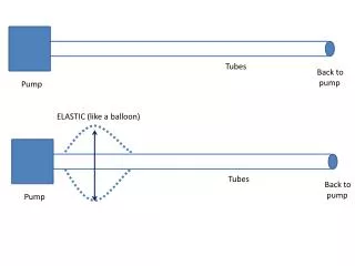
Energy Loss in Valves • Function of valve type and valve position • The complex flow path through valves can result in high head loss (of course, one of the purposes of a valve is to create head loss when it is not fully open) • Ev are the loss in terms of velocity heads