Download

1 / 40
440 likes | 625 Vues
An Extended Pinch Analysis and Design Procedure utilizing Pressure Exergy for Subambient Cooling A. Aspelund, D. O. Berstad, T. Gundersen The Norwegian University of Science and Technology, NTNU Department of Energy and Process Engineering, NO-7491 Trondheim, Norway. CHISA/PRES 2006 in Prague.

E N D
An Extended Pinch Analysis and Design Procedure utilizing Pressure Exergy for Subambient Cooling • A. Aspelund, D. O. Berstad, T. Gundersen • The Norwegian University of Science and Technology, NTNU • Department of Energy and Process Engineering, NO-7491 Trondheim, Norway CHISA/PRES 2006 in Prague
Outline of the Presentation • Motivation and Background • Introducing the ExPAnD Methodology • Objectives and Scope • Exergy and what we can do with Pressure • General Process Synthesis revisited • The Onion Diagram revisited • Briefly about the Methodology • A liquefied Energy Chain based on LNG • Application of ExPAnD to the LNG Process • Concluding Remarks
Motivation and Background • Stream Pressure is an important Parameter in above Ambient Heat Recovery Systems • Pressure Levels of Distillation Columns and Evaporators affect important Heat Sources and Heat Sinks (i.e. large Heat Duties) • Below Ambient, Pressure is even more important • Temperature is closely related to Pressure through Boiling and Condensation • Temperature is closely related to Power through Expansion and Compression (i.e. changing Pressure) • Basic Pinch Analysis only considers Temperature • Exergy Analysis can handle both Temperature and Pressure, as well as Composition (Process Synthesis)
The ExPAnD Methodology(Extended Pinch Analysis and Design) • Will combine Pinch Analysis (PA), Exergy Analysis (EA) and Optimization/Math Programming (OP) • PA for minimizing external Heating and Cooling • EA for minimizing Irreversibilities (thermodynamic Losses) • OP for minimizing Total Annual Cost • Preliminary and Extended Problem Definition • “Given a Set of Process Streams with Supply State (Temperature, Pressure and the resulting Phase) and a Target State, as well as Utilities for Heating and Cooling Design a System of Heat Exchangers, Expanders and Compressors in such a way that the Irreversibilities are minimized”
Objectives and Scope • Short Term Objective • Utilize Pressure Exergy for Subambient Cooling • Long Term Objective • Develop a more general Methodology with Graphical and Numerical Tools for Analysis, Design and Optimization of complex Energy Chains and Processes, where Pressure is included as an important Design Variable • Current Scope • Do not consider Systems with Chemical Reactions, thus Composition Effects and Chemical Exergy is omitted • Assume that changes in Kinetic and Potential Energy are neglectable, thus Mechanical Exergy is omitted
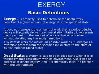
Classification of Exergy e(tm) = (h – h0) – T0 (s – s0) Thermomechanical Exergy can be decomposed into Temperature based and Pressure based Exergy
T T T Q Q Q T Q What can we do with Pressure? Consider a Cold Stream: Ts Tt and Ps Pt
T T Q Q So, we can shape the Composite Curves to best suit our “Purpose” Given a Stream with Supply and Target State, there is a Geometric Region of the Composite Curves that shows all possible TQ-paths in the Diagram
Glasser, Hildebrand, Crowe (1987) Attainable Region Applied to identify all possible chemical compositions one can get from a given feed composition in a network of CSTR and PFR reactors as well as mixers Hauan & Lien (1998) Phenomena Vectors Applied to design reactive distillation systems by using composition vectors for the participating phenomena reaction, separation & mixing General Process Synthesis revisited We would like to “ride” on a “Pressure Vector” in an Attainable Composite Curve Region for Design of Subambient Processes
Possible TQ Routes from Supply to Target State Target State Supply State The Route/Path from Supply to Target State is formed by Expansion & Heating as well as Compression & Cooling a) A Hot Stream temporarily acts as a Cold Stream and vice versa b) A (Cold) Process Stream temporarily acts as a Utility Stream c) The Target State is often a Soft Specification (both T and P) d) Phase can be changed by manipulating Pressure The Problem is vastly more complex than traditional HENS
The “forgotten” Onion The “traditional” Onion S H U R C & E S H R Smith and Linnhoff, 1988 The User Guide, 1982 The “subambient” Onion C & E S H U R Aspelund et al., 2006 The Onion Diagram revisited
A brief Overview of the Methodology • Exergy Analysis is used for Targeting • Can the Cooling be done without External Utilities with maximum utilization of Pressure (including Heat Transfer Irreversibilities)? • If yes, what is the required Exergy Efficiency of the System? • Pinch Analysis is used after each change (Expansion or Compression) to evaluate the Progress of Design • Would like to develop Limiting TQ Profiles • 10 Heuristic Rules have been developed • A Design Procedure (as a flow diagram) for utilizing Pressure Exergy in a Cold Stream to cool a fixed Hot Stream (starting in the Cold End) has been developed • 6 different Design Criteria can be used
The Paper has 2 Examples • A simple 1 hot and 1 cold stream problem • illustrates the use of Pressure Exergy for Subambient Cooling • suggested reading to catch our ideas • A bit more involved problem taken from a real industrial situation (offshore LNG) • applies the ExPAnD Methodology • will be explained by Audun Aspelund
GrCC CC The Simplest possible Example H1: Ts = -10C Tt = -85C mCp = 3 kW/K QH1 = 225 kW Ps = 1 bar Pt = 1 bar C1: Ts = -55C Tt = 10C mCp = 2 kW/K QC1 = 130 kW Ps = 4 bar Pt = 1 bar QH,min = 60 kW QC,min = 155 kW for Tmin = 10C Insufficient Cooling Duty at insufficient (too high) Temperature, but we have cold Exergy stored as Pressure Exergy !!
Exergy Analysis using simplified Formulas and assuming Ideal Gas with k = 1.4 gives: H1: EXT = 65 kW EXP = 0 kW EXtm = 65 kW Inevitable Losses due to Heat Transfer at Tmin = 10C: EXLoss = 14 kW C1: EXT = -20 kW EXP = -228 kW EXtm = -248 kW Exergy Surplus is then: EXSurplus = 248 – (65 + 14) = 169 kW Required Exergy Efficiency for the Heat Exchange Process: X = 65/248 = 26.2 % Targeting by Exergy Analysis It should be possible to design a Process that does not require external Cooling First attempt: Expand the Cold Stream from 4 bars to 1 bar prior to Heat Exchange
CC GrCC After pre-expansion of C1 Modified Composite and Grand Composite Curves Evaluation: New Targets are: QH,min = 60 kW (unchanged) and QC,min = 12.5 kW (down from 155 kW) Power produced: W = 142.5 kW (ideal expansion) Notice: The Cold Stream is now much colder than required (-126C vs. -85C - Tmin)
CC GrCC Pre-heating before expansion of C1 Modified Composite and Grand Composite Curves Evaluation: New Targets are: QH,min = 60 kW (unchanged) and QC,min = 0 kW (eliminated) Power produced: W = 155 kW (ideal expansion) Notice: The Cold Stream was preheated from -55C to -37.5C Temperature after Expansion is increased from -126C to -115C
CC GrCC Expanding C1 in two Stagesto make CCs more parallel Modified Composite and Grand Composite Curves Evaluation: New Targets are: QH,min = 64 kW (increased) and QC,min = 0 kW (unchanged) Power produced: W = 159 kW (ideal expansion) Reduced Driving Forces improve the Exergy Performance at the Cost of Area This was an economic Overkill
O2 Air Separation ASU Oxyfuel Power Plant W Air NG LNG LIN H2O NG LNG Natural Gas Liquefaction CO2 Liquefaction CO2 LCO2 This Presentation Liquefied Energy Chain based on LNG
The Base Case Heat Recovery first, Pressure Adjustments subsequently
PA for the base case Heuristic 7: A fluid with Ps < Pt should be compressed in liquid phase if possible to save compressor work.
EPA after pumping the LCO2 to 65 bar Heuristic 9: If a cold liquid stream to be vaporized does not create a Pinch point, it should be pumped to avoid vaporization at constant temperature, reduce the total cooling duty and increase the pressure exergy. Work and cooling duty should be recovered by expansion of the fluid in the vapor phase at a later stage
EPA after pumping the LIN to 100 bar Heuristic 4: Expansion of a vapor or dense phase stream in an expander will provide cooling to the system, and at the same time generate power. Hence, expansion should preferably be done below Pinch. In subambient processes, a stream with a start pressure higher than the target pressure should always be expanded in an expander (not a valve) if the stream is located below the Pinch point
EPA after two stage expansion of the LIN Heuristic 10: Compression of a hot gas stream to be condensed will increase the condensation temperature. The latent heat of vaporization will also be reduced. Hence, work is used to increase the driving forces and reduce the heating requirements
EPA after compression of natural gas to 100 bar Heuristic 6: A gas or dense phase fluid that is compressed above the Pinch point, cooled to near Pinch point temperature and then expanded will decrease the need for both cold and hot utilities. Additional work is, however, required
EPA after re-compression of the nitrogen We are done !
Conclusions LNG Process • By using LIN and LCO2 as cold carriers, LNG can be produced offshore with an exergy efficiency of 85.7 % • The offshore process: • Is self-contained with power • Can operate with little rotating equipment • Can operate without hazardous refrigerants • Can operate without offshore cryogenic loading • Allows a higher fraction of CO2 and HHC in the LNG, reducing the need for offshore gas conditioning and treatment.
Conclusions ExPAnD • The ExPAnD methodology integrates Pinch Analysis and Exergy Analysis (in the future, also Optimization) • The ExPAnD methodology has proven to be an efficient tool for developing energy processes • The methodology shows great potential for minimizing total shaft work in subambient processes • The savings are obtained by optimizing the process streams compression and expansion work together with the work needed to create necessary cooling utilities
Thank you for your AttentionAudun.Aspelund@ntnu.noTruls.Gundersen@ntnu.no