Download

1 / 46
560 likes | 982 Vues
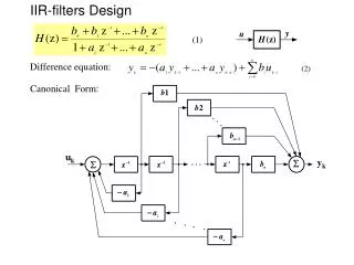
IIR Filters. The general form for z -transform transfer functions for a digital filter is. The inverse of this z -transform transfer function h[n] is the impulse response for this digital filter. As an example if. we have.

E N D
The general form for z-transform transfer functions for a digital filter is The inverse of this z-transform transfer function h[n] is the impulse responsefor this digital filter.
As an example if we have
The inverse z-transform of this transfer function (the impulse response) is h[n] n 1 2 3 4 5
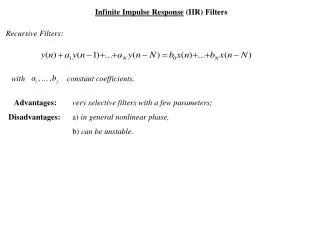
This impulse response function goes on forever. That is, the impulse response is infinite in duration. Such filters are referred to as infinite impulse response or IIR filters.
Another example would be The corresponding impulse response is
h[n] n 1 2 3 4 5 This impulse response is finite in duration. Such filters are referred to as finite impulse response or FIR filters.
Given a transfer function, how do we know whether this transfer function corresponds to an impulse response that is infinite or finite in duration? In our previous two examples we had (IIR) (FIR)
In general, any filter whose transfer function has a denominator (that does not factor-out) will have an impulse response that is infinite in duration corresponding to an IIR filter. Any filter whose transfer function does not have a denominator will have an impulse response that is finite in duration corresponding to an FIR filter.
The distinction between IIR filter transfer functions and FIR filter transfer functions becomes more clear if we look at the corresponding difference equations. In our examples the corresponding difference equations are (IIR) (FIR)
The IIR filter difference equation is recursive in nature: the current output depends upon the previous output Since the current output depends upon the previous output and the previous output depends upon its previous output, the output depends upon the infinite past.
The FIR filter difference equation is depends only upon the input If the input is finite in duration (such as an impulse) then the output is finite in duration. The output depends upon the finite past.
The difference between IIR and FIR filters can also be seen by looking at the transfer functions and noting that the IIR transfer function can be expanded using a geometric series that is infinite: The FIR filter is already in a finite series form.
Most analog filters have an impulse response which is infinite in duration. IIR filters are generally designed by emulating an analog prototype filter. There are two methods for doing this analog filter emulation: (1) the matched z-transform or impulse invariant transform (2)the bilinear transformation. In both cases, we are given an analog transfer function H(s), and we transform this function into a digital transfer function H(z).
The Matched z-Transform In the matched z-transform digital filter design method we try to “match” the impulse response of the analog filter with that of the digital filter being designed. To match the impulse responses, we take the inverse Laplace transform of the analog filter H(s)h(t), then sample the impulse response h(t)h[n], then take the z-transform of the sampled impulse response to get the z-transform transfer function h[n]H(z).
Analog Prototype Digital Filter L-1 Z sample Once we have our z-transform transfer function H(z), we apply the definition of the transfer function to write our digital filter equations:
Example: Use the matched filter design method to design the digital equivalent of an integrator. Solution: The analog transfer function is The inverse Laplace transform is
We then sample the impulse response to get h[n]: Finally, we take the z-transform of the impulse response to get the digital filter transfer function.
Finally, we apply the definition of the z-transform transfer function to get the relationship between the input of the digital filter x[n] and the output of the digital filter y[n].
We see that the output is the summationof the input. Thus the digital filter accurately represents the analog filter. The digital filter does not always accurately represent the analog filter as will be seen in the next example.
Example: Use the matched filter design method to design the following transfer function: where Wc = Ws/4, and Ws is the sampling frequency. Solution: First, we find the impulse response
Then we sample the impulse response: Then we take the z-transform of the (discrete-time) impulse response:
As we can see, it is not much of a low-pass filter: the frequency rolloff is not very great. The reason for this small rolloff is aliasing error: the frequency response of H(z) is composed of copies of the frequency response of H(s) at 0, Ws, 2Ws, etc. The copy at 2Ws overlaps the copy at 0. Aliasing error is an inherent problem in matched filter design. Unless the cutoff frequency is very low compared to the sampling frequency, we will get substantial error due to aliasing. This aliasing problem is solved using the bilinear transformation.
The Bilinear Transformation The bilinear transformation is a fairly direct method of converting H(s) to H(z). Rather than map the analog frequencies W=0 to Ws/2 to the digital frequencies w=0 to w=p (as we had done with the matched z-transform), we will map the analog frequencies W=0 to to the digital frequencies w=0 to w=p Matched z-transform: W=(0,Ws/2) w=(0,p) Bilinear Transformation: W=(0,) w=(0,p)
What kind of function maps W=(0,) w=(0,p)? How about this: As we can see from the graph on the following slide, this function does perform the necessary mapping.
We know the relationship between W and w; what is the relationship between s and z?
Because of the “warped” nature of our transformation, it is necessary to “pre-warp” our analog prototype critical frequencies so as to coincide with the critical frequencies of the corresponding digital filter.
Example: Use the bilinear transformation method to find the digital equivalent to the following transfer function: where Wc = Ws/4, and Ws is the sampling frequency. Solution: First, we must “pre-warp” the analog frequency:
We then substitute our “pre-warped” frequency, and apply the bilinear (sz) transformation:
As can be seen, the frequency response is much improved. At w=0, the response is the same as the analog filter at W=0, and at w=p, the frequency response is the same as the analog filter at W=.
Example: Repeat the previous example where Wc = Ws/6. Solution: Our “prewarping” is slightly different:
Applying the bilinear transformation, we have The frequency plot is given on the following slide.
Example: find the digital equivalent of a second-order Butterworth filter using the bilinear transformation. Let Wc = Ws/4. Solution: The second-order Butterworth filter has the following form: (Enter [b a] = butter(2,1,'s') in MATLAB.)