Download
1 / 30
390 likes | 918 Vues
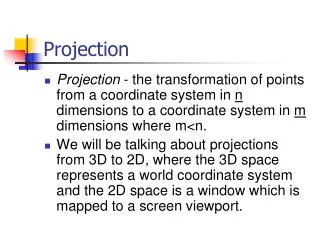
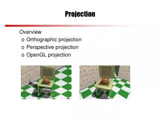
The Projection Matrix. Lecture 29 Mon, Nov 5, 2007. Model Trans. View Trans. Proj Trans. Object Coords. World Coords. Eye Coords. Clip Coords. M. V. P. Lighting Calculations. Clipping. Perspective Divide. Normal Dev Coords. Window Coords. Frame- buffer.

E N D
The Projection Matrix Lecture 29 Mon, Nov 5, 2007
Model Trans View Trans Proj Trans Object Coords World Coords Eye Coords Clip Coords M V P Lighting Calculations Clipping Perspective Divide Normal Dev Coords Window Coords Frame- buffer Rasterization, Shading Hidden-surface Removal, Texture Application The Graphics Pipeline
Homogeneous Coordinates • Points are stored in homogeneous coordinates (x, y, z, w). • The true 3D coordinates are (x/w, y/w, z/w). • Therefore, for example, the points (4, 3, 2, 1) and (8, 6, 4, 2) represent the same 3D point (4, 3, 2). • This fact will play a crucial role in the projection matrix.
Coordinate Systems • Eye coordinates • The camera is at the origin, looking in the negative z-direction. • View frustrum (right – left, bottom – top, near – far). • Normalized device coordinates • -1 x 1 • -1 y 1 • -1 z 1
The Transformation • Points in eye coordinates must be transformed into normalized device coordinates. • But first they are transformed to clipping coordinates.
The Transformation • For example, • The point (r, t, -n, 1) is first transformed to the point (n, n, -n, n). • The point (l(f/n), b(f/n), -f, 1) is first transformed to the point (-f, -f, f, f).
The Transformation • Later, OpenGL divides by the w-coordinate to get normalized device coordinates. • (n, n, -n, n) (1, 1, -1) • (-f, -f, f, f) (-1, -1, 1) • This is called the homogeneous divide, or perspective division. • It is a nonlinear transformation. • It occurs at a later stage in the pipeline.
The Perspective Transformation – x, y • Points in eye coordinates are projected onto the near plane, sort of. • The x- and y-coordinates are projected onto the near plane. • The z-coordinated is scaled to the range [-n, f].
near plane P(x, y, z) t -n -f b The Perspective Transformation – x, y • Consider the projection in the yz-plane.
The Perspective Transformation – x, y • Consider the projection in the yz-plane. near plane P(x, y, z) t y -f -z b
near plane P(x, y, z) t y -f n b The Perspective Transformation – x, y • Consider the projection in the yz-plane. y -z
The Perspective Transformation – x, y • By similar triangles, y/n = y/(-z), • Therefore, • Similarly,
The Perspective Transformation – x, y • Notice that these transformation are not linear. • That is, x and y are not linear combinations of x, y, and z. • Therefore, this transformation cannot be carried out by matrix multiplication. • We will perform the multiplication by n using a matrix, but dividing by -z, i.e., w, will have to be postponed.
The Perspective Transformation – z • The z-coordinate is handled differently because we must not lose the depth information yet. • In the z-direction, we want to map the interval [-n, -f] to the interval [-n, f]. • Later, the perspective division will map [-n, f] into [-1, 1].
The Perspective Transformation – z • Since this is a linear transformation, we will have z = az + b, for some a and b, to be determined. • We need • Therefore,
The Perspective Transformation • That is, we will map (r, t, -n, 1) (nr, nt, -n, n), (l(f/n), b(f/n), -f, 1) (fl, fb, f, f), etc. which is a linear transformation. • These points are equivalent to (r, t, -1), (l, b, 1), etc.
The Perspective Transformation • The perspective matrix is Represents division by –z (perspective division)
The Perspective Transformation • This transforms this frustum… P(x, y, z) t -n -f b
The Perspective Transformation • …into this frustum ft P(x, y, z) nt -n f nb fb
The Perspective Transformation • Later, the perspective division will transform this into a cube. 1 P(x, y, z) 1 -1 -1
The Perspective Transformation • Verify that P1 maps • (r, t, -n, 1) (nr, nt, -n, n) (r, t, -1) • (l, t, -n, 1) (nl, nt, -n, n) (l, t, -1) • (r, b, -n, 1) (nr, nb, -n, n) (r, b, -1) • (l, b, -n, 1) (nl, nb, -n, n) (l, b, -1) • (r(f/n), t(f/n), -f, 1) (fr, ft, -f, f) (r, t, -1) • (l(f/n), t(f/n), -f, 1) (fl, ft, -f, f) (l, t, -1) • (r(f/n), b(f/n), -f, 1) (fr, fb, -f, f) (r, b, -1) • (l(f/n), b(f/n), -f, 1) (fl, fb, -f, f) (l, b, -1)
The Projection Transformation • The second part of the projection maps • (nr, nt, -n, n) (n, n, -n, n) (1, 1, -1) • (nl, nt, -n, n) (-n, n, -n, n) (-1, 1, -1) • (nr, nb, -n, n) (n, -n, -n, n) (1, -1, -1) • (nl, nb, -n, n) (-n, -n, -n, n) (-1, -1, -1) • (fr, ft, -f, f) (f, f, f, f) (1, 1, 1) • (fl, ft, -f, f) (-f, f, f, f) (-1, 1, 1) • (fr, fb, -f, f) (f, -f, f, f) (1, -1, 1) • (fl, fb, -f, f) (-f, -f, f, f) (-1, -1, 1)
The Projection Transformation • The matrix of this transformation is
The Projection Matrix • The product of the two transformations is the projection matrix.
The Projection Matrix • The function glFrustum(l, r, b, t, n, f) creates this matrix and multiplies the projection matrix by it. glMatrixMode(GL_PROJECTION); glLoadIdentity(); glFrustum(l, r, b, t, n, f);
The Projection Matrix • The function gluPerspective(angle, ratio, near, far) also creates the projection matrix by calculating r, l, t, and b. glMatrixMode(GL_PROJECTION); glLoadIdentity(); gluPerspective(angle, ratio, n, f);
The Projection Matrix • The formulas are • t = n tan(angle/2) • b = -t • r = t ratio • l = -r
Question • When choosing the near and far planes in the gluPerspective() call, why not let n be very small, say 0.000001, and let f be very large, say 1000000.0?
Orthogonal Projections • The matrix for an orthogonal projection is much simpler. • All it does is rescale the x-, y-, and z-coordinates to [-1, 1]. • The positive direction of z is reversed. • It represents a linear transformation; the w-coordinate remains 1.
Orthogonal Projections • The matrix of an orthogonal projection is