Download
1 / 28
280 likes | 447 Vues
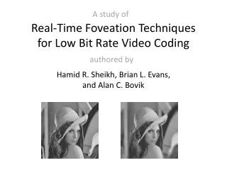
A Hybrid Scheme for Low Bit-Rate Coding of Stereo Images. Jianmin Jiang, Eran A. Edirisinghe University of Bradford, Bradford Loughborough University, Leicestershire IEEE TRANSACTIONS ON IMAGE PROCESSING, FEB 2002. OUTLINE. INTRODUCTION (Stereo Image) AN OVERVIEW OF THE HYBRID SCHEME

E N D
A Hybrid Scheme for Low Bit-Rate Coding of Stereo Images Jianmin Jiang, Eran A. Edirisinghe University of Bradford, Bradford Loughborough University, Leicestershire IEEE TRANSACTIONS ON IMAGE PROCESSING, FEB 2002
OUTLINE • INTRODUCTION (Stereo Image) • AN OVERVIEW OF THE HYBRID SCHEME • CONTOUR ANALYSIS OF STEREO IMAGES • FREE-FORM OBJECT ENCODING • EXPERIMENTAL RESULTS
INTRODUCTION • Stereo Image • Stereo images are constructed by simulating human viewing effect upon observing objects through two horizontally separated positions • Every stereo image can be represented two frames labeled as leftframe and right frame.
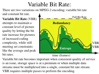
INTRODUCTION (cont.) • If these left and right frames are to be compressed and transmitted independently, the bandwidth required would need to be double. • Efficient compression can be achieved by exploiting redundancies • Intra-frame redundancy • Two constituent images • Inter-frame redundancy • Left and right frames
INTRODUCTION (cont.) • Estimation for disparity or binocular parallax • Intensity based method • Look for correspondence between luminance values (eg. Block matching) • Fixed blocks can’t reflect the true disparity between those free-form objects. • Object based method • Determine objects in both images and seeks correspondence between the two sets (eg. The proposed scheme)
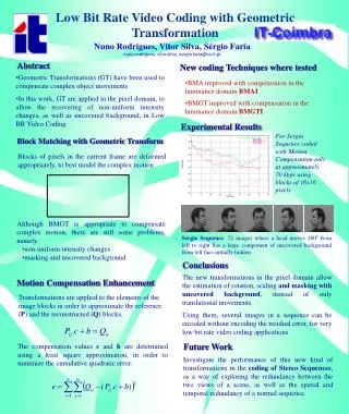
AN OVERVIEW OF THE HYBRID SCHEME Left JPEG Object Disparity iJPEG Block Disparity L-Obj Right Object Extraction & match Block Classify Boundary coder DCT coder R-Obj Interior coder Background coder
CONTOUR ANALYSIS OF STEREO IMAGES • Contour Extraction • Laplacian-of-Gaussian (LoG) operator • ,σ is the standard deviation • The LoG response will be positive on the darker side, and negative on the lighter side intensity The left hand graph shows a 1-D image, 200 pixels long, containing a step edge. The right hand graph shows the response of a 1-D LoG filter with Gaussian=3 pixels
CONTOUR ANALYSIS OF STEREO IMAGES • Contour Extraction (cont.) • Let sx and sy be the slops of the LoG of the image along both x and y directions for some zero-crossing point. • An edge strength at (x, y) is defined as • The contour points are chosen by using a pre-set threshold -3 -1 1 4 -4 -2 4 6 -2 2 1 3 1 1 2 1
CONTOUR ANALYSIS OF STEREO IMAGES • Contour Matching • Closed contours • Open contours • Background = + + … • We use chain codes {ai 0, 1, …, 7} to represent the contours 0 4
CONTOUR ANALYSIS OF STEREO IMAGES • Contour Matching • Closed contours (hui Li, Sanjit k. Mitra, 1995) • Shifting and smoothing the chain codes • We convert the standard chain code {ai} into a modified code {bi} by a shifting operation defined by • e.g. {7,0,7,0,7,0} -> {7,8,7,8,7,8} • e.g. {2,0,7,4} {4,2,1,6} {2,0,-1,-4} {4,2,1,-2} -Mean {3,1,0,-3} Mean = -1 1
CONTOUR ANALYSIS OF STEREO IMAGES smoothing & shifting Chain code smoothing & shifting Chain code
CONTOUR ANALYSIS OF STEREO IMAGES R L • Contour Matching (Closed contours) • Measure of correlation between two n-point segments, one starting at index k of contour L and the other starting at index l of contour R, is defined as: Where {li} and {ri} be the chain code representations of two contours L and R, which corresponds to the left and right frames, and let NL and NR be their lengths • The similarity function FLR = max {MCkl} • If FLR≧ FL’R, where L’ represents all similar contours to R, the best match is selected. k l 0 8 n points segments MCkl=1 when perfect match L R 4
CONTOUR ANALYSIS OF STEREO IMAGES R L • Contour Matching (open contours) • Measure of curvature at the ith point for a contour of length n with chain code {li} • The contour segments surrounding the salient points are then used as 1-D templates in finding the corresponding matches in the other image 2p 2p If Ci ≧Ck for all k [i-p, i+p], where p is a constant, we say this point is a salient point
CONTOUR ANALYSIS OF STEREO IMAGES Left JPEG Object Disparity iJPEG Block Disparity L-Obj Right Object Extraction & match Block Classify Boundary coder DCT coder R-Obj Interior coder Background coder
CONTOUR ANALYSIS OF STEREO IMAGES • Contour Blocking and Classification 8x8 pixels block Internal block External block Boundary block Bounding box Object Bounding Rectangle (OBR) We extend the bounding box such that its width and height are multiples of eight pixels
FREE-FORM OBJECT ENCODING (E.A. Edirisinghe, J. Jiang and C. Grecos 1999) • Padding of left OBR • Extensive experiments indicated that certain trends exist with respect to pixel value variations for boundary blocks. • We want to use a linear equation to predict those exterior pixels immediately next to to the boundary pixels in a row (projected pixel). Projected pixel Interior pixel
FREE-FORM OBJECT ENCODING • Padding of left OBR (cont.) • In a given row, assume there exist n (1 < n < N) consecutive pixels inside the object,which are bounded by a projected pixel on the left or on the right . Let these n pixel values be represented by Pn. Where Xn represents the column number of Pn with respect to the projected pixel N n = 2 N
FREE-FORM OBJECT ENCODING • Padding of left OBR (cont.) • When Pn are bounded by two projected pixels, both projected pixels will be determined using the same linear equation. • If a projected pixel is flanked by interior pixels on both sides, the above process is performed in both directions and the average of the two results is taken. • If n = 1, the projected pixel value is taken to be equal to the single interior pixel value. • Remaining exterior pixels are padded with traditional technique.
FREE-FORM OBJECT ENCODING • Padding of left OBR (cont.) • After all the boundary blocks are padded, the exterior blocks immediately next to the boundary blocks are filled by replicating the samples at the border of boundary blocks with the priority • Boundary block to the left of exterior block • Block at the top • Block to the right • Block at the bottom (lowest priority) • Remaining blocks are filled with value of 128 P 1 5 2 P P 1 P 5 3 P P P P P P 1 5 3 P P 1 2 3 P P P P 3 P P P P P 5 3 P P P P P P P 5 3 P P 1 4 4 4 4
FREE-FORM OBJECT ENCODING Left JPEG Object Disparity iJPEG Block Disparity L-Obj Right Object Extraction & match Block Classify Boundary coder DCT coder R-Obj Interior coder Background coder
FREE-FORM OBJECT ENCODING • Disparity-Based Prediction for Both Boundary Blocks and Internal Blocks • Boundary blocks • Search range [-7,7]. • Alpha plane (L unpadded) • Square error (L padded) Since the stereo pair is produced by observation of the same scene from two horizontally separated positions, disparity between the two frames will only occur horizontally rather than vertically W = [-7,+7] Left obj. Right obj. 0 0 0 1 - )2 x ( 0 0 1 1 1 1 1 1 L R 1 1 1 1 The best match
FREE-FORM OBJECT ENCODING • Disparity-Based Prediction for Both Boundary Blocks and Internal Blocks • Boundary blocks • Error block : • The shape of the right object would be similar to that of its matching left object, so we won’t encode the shape of right OBRs. = {sij} = {mij} R L (padded)
FREE-FORM OBJECT ENCODING • Disparity-Based Prediction for Both Boundary Blocks and Internal Blocks • Internal blocks • Use the two blocks to be pioneering blocks, one at the top and one at the left of the block to be encoded • No overhead bits needed for informing the decoder of which block is chosen in the left frame (J. Jian, E.A. Edirisinghe and H. Schroder 1997) Rij-1 X Ri-1j Rij X
FREE-FORM OBJECT ENCODING Search window |-----N x 8-----| Lij-1 Rij-1 Pioneering blocks Li-1j Lij Ri-1j Rij Block to be encoded Best match L R predictor α,β (0,1], the weight of each block • Use Rij-1 and Ri-1j to compute Rij • Find the best match Lij in L, where L is produced by Lij-1 and Li-1j
FREE-FORM OBJECT ENCODING • Internal texture smooth detection • Calculate the error block and MSE between two matching regions. If MSE is less then some threshold, the error block won’t be encoded. • If MSE is too large, object extraction would be proceeded within current object. matching coding
EXPERIMENTAL RESULTS E.C.R = (bit_NoJ– bit_NoP)/bit_NoJ (Bit_NoJ and bit_NoP: total bits produced in compressing right frames by JPEG and by the proposed algorithm) DCTDP : disparity compensated transform domain predictive coding (block based)
EXPERIMENTAL RESULTS The reference image quality is poor, so matches between objects will produce larger error for both boundary and internal areas.
EXPERIMENTAL RESULTS • Visual inspection for example (right frame) original DCTDP proposed