Download
1 / 92
930 likes | 1.13k Vues
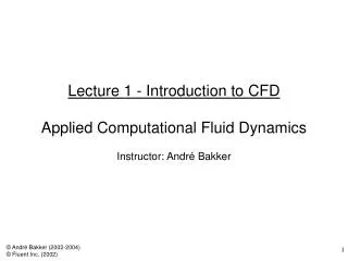
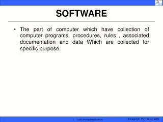
COMPUTER MODELING OF FLUID – STRUCTURE HEAT TRANSFER SOFTWARE fluidyn - MP. PRESENTATION OF fluidyn - MP. General : role & utility of Computational Fluid Dynamics. A reliable numerical representation of a real processus with the help of well adapted physical models

E N D
COMPUTER MODELING OF FLUID – STRUCTURE HEAT TRANSFER SOFTWARE fluidyn - MP
General : role & utility of Computational Fluid Dynamics A reliable numerical representation of a real processus with the help of well adapted physical models Easy to use & adapted to optimisation studies in industrial processes Economic with a security advantage Ideal complementary tool for experimental measurements Access to physical variables (velocities, pressure, temperature, etc.) at each point in the domain
Software fluidyn - MP, CHT Model Strong coupling & conjugate heat transfer between fluid & structures integrated in a single software platform Robust physical models & various well adapted solvers Finite Volume Method for fluids and Finte elements method for structures Automatic exchange of boundary conditions between fluids & structures - Adaptative Fluid Mesh Local time step used to reduce CPU time
Fluid Solver Solution of Navier-Stokes Equations 3-Dimensions Compressible / incompressible Mechanical / thermal shocks Viscous / non-viscous Laminar / turbulent Multi-species Multi-phase
Fluid Solver Non-Newtonian Flows : Bingham law Power law Chemical – combustion reactions Arrhenius model Eddy-break-up model Eddy dissipation model Deflagration & fire BLEVE Pool fire Detonation JWL model Two phase flows droplets, bubbles, particles Euler-Lagrange Monte-Carlo, Free surface flow ( VOF method + CSF method)
Fluid Solver Turbulence Models Algebraic Models • Baldwin- Lomax Mixing Length : • Van Driest damping • Abbott & Bushnell • Cebeci- Smith Sub grid scale model SGS Two equations transport (k - e) & RNG Reynolds stress model (anisotropic turbulence)
Fluid Solver Equations of State Perfect gas Ideal gas JWL (Jones - Wilkins - Lee) for explosions Linear - polynomial User defined Viscosity & Prandtl number Temperature functions User defined
Fluid Solver Spatial discretization schemes Explicit: Van Leer Flux Vector Splitting Roe Flux Difference Splitting 3rd order Advection Upwind Splitting, HLLC Semi- implicit : Weighted Upwind Scheme QSOU 2nd order Implicit : Central Difference Scheme 3rd order Flux Limiter Scheme (Van Leer, SMART, etc.)
Fluid Solver Temporal discretization scheme Explicit : Time step • global minimum for transient simulations • local for steady state simulations convergence acceleration Temporal Integration • 6 step 2nd order Runge Kutta. Implicit: Gauss-Seidel or Jacobi iterative methods steady state calculation & low velocities.
Combustion Modelling 3 available models Arrhenius Model coefficients of chemical reactions linked to Arrhenius parameters & activation temperatures EDC Model (Eddy Dissipation Concept) Magnussen formula used to link the intermittent turbulent flame to the turbulent dissipation rate Minimum of the Arrhenius model & EDC adapted to high velocity turbulent flows Monitoring combustion gases (CO, CO2, NOX...) & smoke, dispersion
Radiation Modelling Finite Volumes computation in the fluid Radiation Models Transparent Media • Automatic calculation of 3D view factors • Shadow effect of intermediate obstacles Opaque Media • Six-Flux model • Discrete ordinate model Collaboration with research laboratories (EM2C laboratory of Ecole Centrale, Paris) et industries (CIAT) for heat transfer modelling
Convection / conduction modelling Convection finite volumes computation in the fluid automatic computation of heat transfer coefficient in fluid - structure high order spatial solution schemes (3rd order) Conduction finite elements computation in the structure (beams, shells, tetrahedrals, etc.) computation with an adapted local time step Strong coupling with automatic exchange of boundary conditions between fluid & structures
Structured solver • Finite Elements • beams • shells • tetrahedral, hexahedral • bricks, springs, etc. • Material characteristics • Linear elasto-plastic, orthotropic • Piecewise linear • Non linear plastic
Structured solver Small deformations & large displacements Finite Elements method Large deformations Finite Elements method Finite Elements solvers Explicit / implicit Rayleigh damping
Structured Solver • Boundary Conditions • Transient or constant • Outside : at nodes : temperature, forces, displacements at faces: pressure, volume forces • Imposed automatically in fluids & structures • Modelling displacement of fluid mesh with UpdatedLagrangian method
Fluid solver • Fluid temperature • Heat transfer coefficient • Distribution of boundary pressures Iterations until convergence • Thermal solver • Transient heat transfer • Solid temperature • Structured solver • Thermal load • Mechanical load (pressure) • stress & deformations FLUID-STRUCTURE REMESHING Computation Procedure - 4 steps
Pre - processor Mesh Multi-block structured Un-structured • Delaunay method • 2D & 3D meshes • Hybrid, tetrahedral or hexahedral mesh Adaptative mesh • Shocks, turbulent boundary layers, .. • Refined mesh & automatic interpolation of the solution. Interactive, simple & automatic Complex geometries
Post - processor Geometry & computation parameters visualisation during simulation. 3D colour visualisation. Multi-viewport facility : upto 30 viewports Comparison of results obtained from different computations Vectors, iso-contours, iso-surfaces & 3D current lines Translations, rotations, multi projections XY plots: residual & other parameters Animations
Examples of studies conducted with fluidyn - MP Modelling of Fluid Structure Heat Transfers Fire in a train compartment Afterburner Riser Exchanger slab (CIAT) Waste incinerator Refrigerator Cooling metal Pipe with 2 fluids (high pressure)
CASE 1 Fire in a train compartment
Two phases : • Simulation of code calibration in the case of fire modelling in an enclosure • experimental results : sample compartment consisting of • a seat & a ventilation system • reproduction of heat phenomenon • (convection + radiation) • optimisation of principal parameters : • smoke rates • coefficient of smoke absorption • distribution of chemical energy of the burned seat as • radiative & convective energy • mesh Study Framework Simulation done for the whole car (complex geometry, Multiple boundary conditions)
Compartment mesh Boundaries conditions VENTILATION AND FIRE INSIDE A COMPARTMENT Phase 1 : geometry
Trace points position Calibration with experience VENTILATION AND FIRE INSIDE A COMPARTMENT Phase 1 : Model setting
Geometry and boundaries conditions VENTILATION AND FIRE INSIDE A WHOLE CARRIAGE Phase 2 : geometry
Velocities field on a cross section VENTILATION & FIRE IN A WHOLE CAR Phase 2 : Results
Temperature (°C) 900 seconds after the beginning of fire Phase 2 : Results
Evolution of temperature VENTILATION & FIRE IN A WHOLE CAR Phase 2 : Results
Phase 2 : Results Temperature evolution in a compartment VENTILATION & FIRE IN THE COMPLETE CAR
Temperature at t=900s Roof Phase 2 : Results
CASE 2 Heat exchanges in a exchanger slab
Description • Cooling in one of the fin tubes of an exchanger by air flow • Dimensions of the fin tube = 100 × 45 × 0.5 mm • Fin tube material = aluminium • Cooling fluid circulating in the tubes, T = 25°C. • External temperature (air) = 10°C. • Inlet air velocity = 2 m/s • Simulation until temperature stabilisation in the structure Study framework
Tube with refrigerant air inlet outflow fluid fluid radiating plate Geometry
Structure mesh : Finite Elements / Fuid mesh : Finite Volumes MP Mesh
MP pressure field Results
MP MP velocities field Results
temperature in the fluid MP MP Results
MP temperature field Results
MP temperature in the structure Results
CASE 3 Heat Exchanges in a refrigerator
Description • The refrigerator has 4 compartments separated by 3 slabs cooled by a cooler (- 90°C). • Dimensions of the refrigerator = 128.5 × 55 × 74 cm • The compartments are interconnected behind the refrigerator. • The refrigerator is insulated by a polyurethane layer. • Insulator thickness : 8 mm cm on the panel in front, 12 cm in the rest • The external temperature is 20°C. • The heat transfer across the insulation involves the natural convection currents in the compartments. • Simulation time= 100 min (temperatures stabilised in the insulator & in the refrigerator) Study framework Air Polyurethane = 1.972 kg/ m3 = 48.053 kg/ m3 µ = 1.23e-5 Pa.s k = 0.025 W/mK Cp = 1007.4 J/kgK Cp = 400 J/kgK Pr = 0.744 = 0.0055
Mesh Top view Transverse View
Temperature contours in the compartments along X axis Results