Download
1 / 13
130 likes | 210 Vues
Temperature rise of SVD2 IR beampipe during single beam study. Samo Stani č, SVD Meeting 2003/10/30. Single beam study LER I max =1A, i max =0.84 mA n b = 1187 bunches (1 train, fill pattern 10x4+1x5) HER I max =0.6A, i max =0.805 mA n b = 745 bunches

E N D
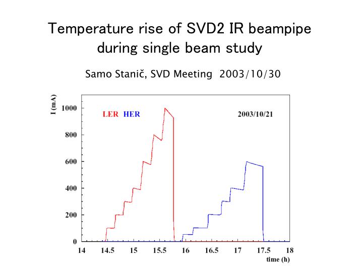
Temperature rise of SVD2 IR beampipe during single beam study Samo Stanič, SVD Meeting2003/10/30
Single beam study LER Imax=1A, imax=0.84 mAnb=1187 bunches (1 train, fill pattern 10x4+1x5) HER Imax=0.6A, imax=0.805 mAnb=745 bunches (16 trains, fill pattern 10x4+1x5, gap 120 buckets) HOM power estimate in Be PHOM = kl I2 / (fb nb) = kl i2 nb / fb fb = 100 kHz kl (Be) = 0.01-0.02 V/pC (ABCI est. for BL=6mm) Pgen(LER)= 85-170W Pgen(HER) = 50-100W Pmax(LER)= 4-9W Pmax(HER) = 2-5W (assuming max 5% goes into heat)
SVD2 IR beampipe temp. sensors 7 sensors in BWD (incl. 1 on and 1 behind Cu Cooling block) 8 sensors in FWD (incl. 1 on and 1 behind Cu Cooling block) 6 sensors on Be 7 24 4 sensors on manifolds
RTD Around the manifold Behind cooling block On manifold On Be On cooling block
RTD under BWD mask RTD on Be staggered in phi (2 are hidden) RTD behind BWD Cu block
Locations of temp. sensors on the beampipe: full phi and z coverage
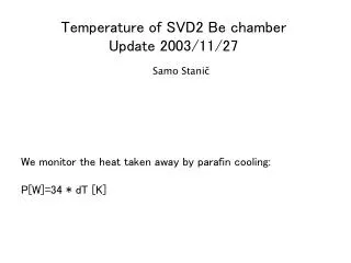
We know exact temperatures of paraffin before and after Be (in the both manifolds)
Quadratic fit of the temperature difference between in- and out-flowing paraffin T(I) =Tconst +dT(I) T(ILER)= 0.2+0.3 I2 T(IHER)= 0.2+0.6 I2 dT(ILER= 1A)=0.3 deg dT(ILER=1.8A)=1.0 deg dT(ILER=2.5A)=1.9 deg dT(IHER=0.6A)=0.2 deg dT(IHER=1.2A)=0.9 deg dT(IHER=1.5A)=1.4 deg
Heat deposit in Be: dTLER=0.3 deg dTHER=0.2 deg dm/dt=0.88kg/min (1.1l/min) Cp=2300kJ/kg/K P=dm/dt * Cp * dT Pmeas(LER) = 10W P[W]=34 * dT [K] Pmeas(HER) = 7W If we extrapolate dT(I): Pext(ILER=2.5A) = 65W Pext(IHER=1.5A) = 50W The fit of present data is close to design value for Be (100W) Single beam study with larger currents would help…
Be pipe LER side (paraffin inlet) Tmp(11): beampipe z=101mm from IP LER 1A/HER 0.6A dT=0.28 deg LER 1.8A/HER 1.2A dT=0.72 deg LER 2.5A HER 1.5A dT=1.19 deg
Be pipe HER side (paraffin outlet) Tmp(28): beampipe z=-54mm from IP LER 1A/HER 0.6A dT=0.5 deg LER 1.8A/HER 1.2A dT=1.8 deg LER 2.5 HER 1.5A dT=3.17deg
Hot spot LER side Tmp(7): beampipe z=160mm from IP (after Cu cooling block) LER 1A/HER 0.6A dT=3.6 deg LER 1.8A/HER 1.2A dT=12.5 deg LER 2.5 HER 1.5A dT=22.1 deg
Hot spot HER side Tmp(24): beampipe z=-105mm from IP (after Cu cooling block) LER 1A/HER 0.6A dT=1.8 deg LER 1.8A/HER 1.2A dT=10 deg LER 2.5 HER 1.5A dT=18.5deg