Download
1 / 22
220 likes | 320 Vues
Global Readout System for the AGATA experiment. M. Bellato a. a INFN Sez. di Padova, Padova, Italy. AGATA Experiment:. x 180. 36 fold segmented crystal + central core contact. 4 p array of HPGe detectors for in-beam g -ray spectroscopy.

E N D
Global Readout System for the AGATA experiment M. Bellatoa aINFN Sez. di Padova, Padova, Italy
AGATA Experiment: x 180 36 fold segmented crystal + central core contact 4parray of HPGe detectors for in-beam g-rayspectroscopy Digital electronics and sophisticated Pulse Shape Analysis algorithms Operation of Ge detectors in position sensitive mode -ray tracking
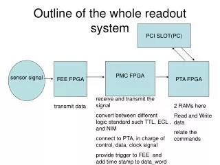
AGATA Readout: The design of FE readout and L1 trigger follows a synchronous pipeline model: the data are collected at 100 MS/s and stored in pipeline buffers at the global AGATA frequency waiting the L1 decision Central trigger processor Central core processing Local Level Trigger Global Trigger Global time reference Global Trigger and Synchronization control system (GTS) Channel per crystal: 36 + 1 per crystal Total channel: 6660
Choice of Readout Standard • Candidates • VME/VXI • Past Experience with older detectors • Bandwidth limited • CompactPCI • First version of AGATA Readout electronics • Advanced TCA • Present version
VME • Pros • Very stable • Huge choice of commercial boards • Slave implementation very simple • Wide ecosystem in HEP • Recently extended with serial switched capabilities • Cons • Slow readout (max 40-80) Mbytes/s • Enhancements (CBLT) not fully standard • Limited power dissipation per slot • Master implementation not trivial • If large estate needed then 9U crates expensive • Limited customizability on the bus • Crate control not standard • No power redundancy -> limited availability
CompactPCI • Pros • Fast ( > 500 Mbytes/s) • Huge choice of commercial boards • Low cost (Telecom standard) • Wide choice of IP cores available for interfacing (both initiator/target) • Extended to serial switched with CPCIExpress • Highly customizable through user reserved backplane connectors • Cons • Small estate • Low power dissipation per slot • Low no. of slots per bus without bridging • No standard crate control
Advanced TCA • Pros • Ultra high speed • Multi standard • Big estate / high power per slot • Choice of star or full mesh backplane • Redundant power supply • Standard crate control • Fits perfectly with modern FPGAs/ ASSPs • Gaining momentum in HEP community • Custom deployments can co-exist with standards • Cons • Moderate choice of COTS cards on the market • Commercial switches exist only for 1G/10G ethernet • Telecom driven
Carrier Readout (1): LLP Carrier Gigabit Ethernet Switch Main FPGA PSA Farm Segment DP RAM Dual star ATCA network
Carrier Readout (2): PCI Express optical translator LLP Carrier PCI Express x1 @ 2.5 Gbps Optical Transceiver PCI Express Endpoint Main FPGA Segments Full mesh ATCA network DP RAM Virtual I/O multiprocessor system
Clock Distribution From GTS Tree
(***) User SFP could be used as 1GEnet or PCIExpress DAQ without FABRIC MGT clocking layout MGT Clocking Layout RocketIO 101 RTM PCI EXPRESS LANE1 A B MUX RTM PCI EXPRESS LANE0 MGTclk M34/N34 RocketIO 102 200MHz GTS Clock USER SFP TRANSCEIVER MUX A B MGTclk AP28/AP29 RocketIO 103 ATCA FABRIC CH11-CH12 MUX A B PHASE LOCKED RocketIO 105 100MHz GTS Clock A B MUX ATCA FABRIC CH9-CH10 INSPECTION PADS RocketIO 106 LOCAL 100MHz (EPSON) A B ATCA FABRIC CH7-CH8 MUX RocketIO 109 ATCA FABRIC CH5-CH6 A B MUX MGTclk AP3/AP4 RocketIO 110 ATCA FABRIC CH1-CH2 A B MUX 100250MHz PCI Express JITTER ATTENUATOR MGTclk J1/K1 RocketIO 112 A B MUX ATCA FABRIC CH3-CH4 RTM PCI EXPRESS LANE5 RocketIO 113 INSPECTION PADS A B RTM PCI EXPRESS LANE4 MUX (**) The ATCA FABRIC channels are routed from CHANNEL1 to CHANNEL12 by switches RocketIO 114 RTM PCI EXPRESS LANE3 OPTICAL SFP A B MUX RTM PCI EXPRESS LANE2
Carrier Power Supply 4x LTM4600 55W DC to DC Converter P3V3-5A 16.5W P3V3/P2V5 Linear Reg P2V5-1.5A VCCAUX Fpga 1 MEZZANINE 1 DC to DC Converter Fusing Filtering Protection Hot Swap P3V3-5A 16.5W MEZZANINE 2 P5V0/P2V5 Linear Reg P2V5-1.5A VCCAUX Fpga 2 -48V DC DC to DC Converter P5V0/P2V5 Linear Reg P2V5-1.5A P3V3-5A 16.5W MEZZANINE 3 VCCAUX MGT DC to DC Converter P5V0/P1V8 Linear Reg P1V8-0.5A P3V3-5A 16.5W MEZZANINE 4 PROMS ENABLE P5V0/P1V2 Linear Reg P1V2-0.5A ATC210 (210W) VTTTXs P12V-14.7A 176.7(160.6)W M48/P12 DC DC P5V0-6A 30W P5V0/P1V2 Linear Reg P1V2-0.5A VTTRXs P12/P5V0 DC DC M48V-4.0A 194.4(176.7)W P3V3_BOOT P3V3-7A 23.1W P12/P3V3 DC DC MAIN BOARD P12/P2V5 DC DC P2V5-7A 17.5W MAIN BOARD P12/P1V2 DC DC P1V2-7A 8.4W FPGAs CORE DC-DC Efficency is estimated at least 90% P12/P1V2 DC DC P1V2-4A 4.8W FPGA MGT P12/P1V8 DC DC P1V8-6A 10.8W MGT BUFFERS 6x LTM460055W
Carrier main features 1M x 18 true dual port RAM @ 100/200 MHZ 800Mb/s LVDS streaming on data channels Equalized and filtered distribution of 200MHZ GTS clock 1 PCI Express/ GE optical link 15 x Full mesh connectivity on the backplane Pervasive I2C bus for slow controls 200W power supply Multiple options for data readout
PCI Express Readout Test Int *ATCA0 = 0xfe001000; // DPRAM on board 0 Int *ATCA1 = 0xfe002000; // DPRAM on board 1 …. Fragment0 = memcpy(buffer0, ATCA0); Fragment1= memcpy(buffer1, ATCA1);