Download
1 / 61
630 likes | 797 Vues
Chapter 7: Anemometry Methods of Measurement: wind force heat dissipation speed of sound calibration exposure wind data processing Anemometer notes. Wind Measurement. The function of an anemometer is to measure some or all components of the wind velocity vector.

E N D
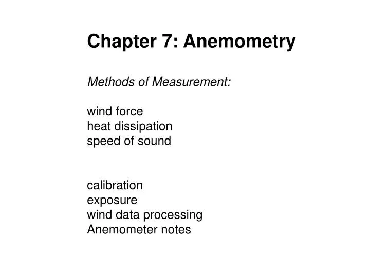
Chapter 7: Anemometry Methods of Measurement: wind force heat dissipation speed of sound calibration exposure wind data processing Anemometer notes
Wind Measurement The function of an anemometer is to measure some or all components of the wind velocity vector. It is common to express the wind as a two-dimensional horizontal vector since the vertical component of the wind speed is usually small near the earth’s surface. Sometimes it is important to consider the vertical component of the wind and then the wind vector is three dimensional. The vector can be written as orthogonal components (u, v, and w) where each component is the wind speed component blowing in the North, East, or vertically up direction.
Wind Measurement The vector can be written as a speed and a direction. In the horizontal case, the wind direction is the direction from which the wind is blowing measured in degrees clockwise from the north. The wind vector can be expressed in three dimensions as the speed, direction in the horizontal plane as above, and the elevation angle. Standard units for wind speed are m s-1 and knots (nautical miles per hour). WMO standard is 10 min average.
Methods of measurement What would the ideal wind sensor be like? The ideal wind-measuring instrument would respond to the slightest breeze yet be rugged enough to withstand hurricane force winds. It would respond to rapidly changing turbulent fluctuations, have a linear output, and exhibit simple dynamic performance characteristics. It is difficult to build sensors that will continue to respond to wind speeds as they approach zero or will survive as winds become very large. Thus a variety of wind sensor designs and within a specific design type, a spectrum of implementations have evolved to meet our needs.
Wind force: The drag force of the wind on an object, which we have all experienced, can be written as Fd= ½(Cd ρAV2) Cd = drag coefficient, a function of the shape of the device and of the wind speed. It is dimensionless and 0< Cd <1. The dependence of the drag coefficient on wind speed is weak over a wide range of wind speeds and is therefore often assigned a value that is a function of shape alone. The air density ρ, has units of kg m-3 the cross-section area of the sensor A in in m2 while V is the wind speed, m s-1. For some sensors, the wind speed must be taken as a vector quantity and then V2 is replaced by V|V|.
Cup and Propeller Anemometers Cup anemometer turns in the wind because the drag coefficient of the open cup face is greater than the drag coefficient of the smooth, curved surface of the back of the cup.
Cup and Propeller Anemometers Cup anemometer turns in the wind because the drag coefficient of the open cup face is greater than the drag coefficient of the smooth, curved surface of the back of the cup (7-1). Before the cup anemometer starts to turn, the effective wind speed is just Vi. Then as the cup wheel rotates, the effective speed is the relative speed Vi-S for the cup (on the left in Fig 7-1) and Vi+S for the cup on the right. But, the difference in drag coefficients dominates, so the cup continues to turn.
R S S Vi + S Wind Speed, Vi Figure 7-1. Wind Force acting on cups
Frequency Speed Shaft Rotation Cup/Prop Cup and Propeller Anemometers The raw output of a cup or propeller anemometer is the mechanical rotation rate of the cup wheel (and supporting shaft). The static sensitivity, nearly constant above the threshold speed, is a function of the cup wheel or propeller design. Threshold Speed: is defined as the wind speed that first moves the cup. This is the anemometers threshold. Most are on the order of ~0.2 – 1 m s-1.
Cup and Propeller Anemometers Typical values of static sensitivity are 30-60 rpm/m s-1 for cups and 180-210 rpm/m s-1 for propellers. A propeller always rotates faster than a cup wheel in the same wind. While a cup wheel responds to the differential drag force, both the drag and lift forces act to turn a propeller. The shaft of an anemometer is coupled to an electrical transducer which produces an electrical output signal, typically a DC voltage proportional to shaft rotation rate and therefore to wind speed.
Cup and Propeller Anemometers The shaft of an anemometer is coupled to an electrical transducer which produces an electrical output signal, typically a DC voltage proportional to shaft rotation rate and therefore to wind speed. An AC transducer may be used which produces an AC voltage with amplitude and frequency proportional to rotation rate. Another option is an optical transducer that generates a series of pulses as an optical beam is interrupted. The pulse rate is proportional to rotation rate.
Cup and Propeller Anemometers: Threshold Cup and propeller anemometers are linear over most of their range, with a notable exception at the lower end of the range. Since anemometers are driven by wind force which is proportional to the square of the wind speed, there is very little wind force to overcome internal friction when the wind approaches zero. This wind speed, called the threshold wind speed, below which the anemometer will not turn. The starting threshold for wind speed slowly increases from zero is much higher than the stopping threshold.
Cup rotation rate (Hz) 2 3 4 5 1 Wind Speed Tunnel (m/s) Figure 7-3
Cup and Propeller Anemometers: Threshold This is because the running friction is much less than static friction. Despite this, the lower range limit is often defined to be zero. The upper limit is the maximum wind speed the anemometer can sustain without damage.
Wind Vane A wind vane is a flat plate or airfoil that can rotate about a vertical shaft and, in static equilibrium, is oriented along the wind vector. There is usually a counter weight to balance the vane about the vertical shaft. The most common electrical transducer is a simple pot (potentiometer) mounted concentrically with the vertical shaft to convert azimuth angle (0° - 360°) to a voltage proportional to that angle. The only source of static error is misalignment of the vane. While it is fairly easy to align a vane to true North, human error frequently causes misalignment.
Wind Vector R Vane Vertical axis of rotation Wind Vane A vane uses a combination of the lift and drag forces on the vane to align itself with the wind vector. Since the vane has a moment of inertia and aerodynamic damping, there is a dynamic misalignment error due to the changing wind direction. See Equation 7.7.
Wind Vane The ideal wind vane would have the following characteristics: Low friction bearing Statically balanced (using counterweight) Maximum wind torque and minimum moment of inertia Damping ratio 0.3 Low threshold wind speed (0.5 m/s) Rugged design capable of wind speeds up to 90 m/s. (hurricane survival) Maintenance requirements are simple: Verify low bearing friction Verify mechanical integrity (check for bent vane arm) Verify alignment to North Verify proper operation of transducer.
Pitot-Static Tube The pitot-static tube is actually a pair of concentric tubes. The stagnation port, at the end of the tube, is a blunt obstacle to airflow and therefore the drag coefficient is unity. The static port is located at a point far enough back along the tube to have no dynamic flow effects at all, so the pressure observed there is just the ambient atmospheric pressure. The pitot-static tube must be oriented into the airflow. A typical tube will tolerate misalignment errors up to ±20°. But it is this alignment problem that makes them virtually unsuitable for atmospheric work!
P-static Pitot-Static Vi P-stagnation Pitot-Static Tube Static ports wind Stagnation port P-static P-stagnation
Pitot-Static Tube They are ideal for wind tunnels and are frequently used to calibrate other anemometers. p-static = p, the ambient atmospheric pressure p-stagnation = 0.5ρV2 + p, thus the differential pressure, Δp=(p-stagnation)-(p-static) = 0.5 ρV2 . The calibration equation is
Pitot-Static Tube The calibration being a function of atmospheric pressure and temperature since ρ=p/RT. Since R is the gas constant of dry air, humidity will have an effect, but less than 1%. The Pitot-Static probe is inexpensive but requires high-quality differential pressure sensor to convert the Δp to a useable signal.
Heat Dissipation Hot-wire and hot-film anemometers are used to infer the wind speed from the cooling of a heated wire or film, which is dependent on the mass flow rate (speed and density of the flow) past the sensing element. The response speed of wires and films is a function of the thermal mass of the element. Hot wires are the fastest conventional wind sensors available since they can use very fine platinum wires (down to 5 μm)! Frequency response is 10-100 Hz!
Heat Dissipation In a wire operated in the constant temperature mode, the current I through the sensor is related to the wind speed by King’s law: Where A and B are constants. The equation is applicable above some threshold flow rate that can be as great as 5 m/s. Hot-wire and hot-film anemometers are expensive and power hungry.
Definitions Distance constant: is the distance air flow past a rotating anemometer during the time it takes the cup wheel or propeller to reach 63.2% of the equilibrium speed after a step change in the input wind speed. =Vi Starting Threshold of a cup or propeller anemometer is the lowest wind speed at which the anemometer, initially stopped, starts and continues to turn and produces a measurable signal. Wind run is the average of the scalar wind speed. Direction is ignored.