Download
1 / 25
250 likes | 256 Vues
GASTONE (Gem Amplifier Shaper Tracking ON Events) A prototype Front-End chip for the KLOE Inner Tracker Detector. On behalf of KLOE2 Bari-LNF Collaboration. Outline. KLOE detector upgrade requirements Inner Tracker purpose and requirements prototype detector parameters

E N D
GASTONE (Gem Amplifier Shaper Tracking ON Events) A prototype Front-End chip for the KLOE Inner Tracker Detector On behalf of KLOE2 Bari-LNF Collaboration
Outline • KLOE detector upgrade requirements • Inner Tracker purpose and requirements • prototype detector parameters • Readout device parameters • readout requirements & time constraints • readout data frame • Front-EndElectronicsdevelopment • GASTONE devicedescription • analog and digitalblocks (mainfeatures) • GASTONE Front-EndBoard • prototypetesting • Detector - FE integration • Input protection • RO boards - strip interconnections • Future plans and developments • Conclusions 2
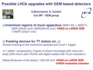
KLOE detector upgrade requirements • Improve vertex reconstruction of KS and decays • 5 tracking layers • from 150 to 250 mm • 200x500 µm spatial resolution • 700 mm active length • 1.5% X0total radiation length • Technology: Cylindrical-GEM Inner Tracker Drift chamber • IT Proto 1.0 (constructed in 2007) • Triple-GEM with 3,2,2,2 gap thickness • 150 mm radius (Layer 1) x 352 mm active length • Electrodes obtained joining 3 foils (450x320 mm2) • 650 µm pitch (only along r) • Anode readout with 1538 strips • One-dimensional readout • 128 chequipped with GASTONE Pisa - 20/12/2019 3
Inner Tracker Purpose and Requirements • Tracking device (NO charge / NO time measurements) • Low gas gain device • High sensitivity head amplifier (few fC) • High density readout (pitch 650m / 35k RO channels) • Low power FE • Most internal layer strip rate < 30 kHz • DC restorer can be avoided • Expected input charge range: 10 50 fC • Stereo strips RO • Cin spread (1 pF ÷ 50 pF) • Very light device (kapton + support structure) • R&D on detector - readout integration
Prototype detector parameters Detector X-ray Test validation • CGEM in current mode • 10x10cm2GEM used as reference (normalization for pressure/temperature effects) • Gain and electron transparency measured • Uniformity measured throughout the whole CGEM surface 6 keV X-ray gun Ref GEM 5
Readout device parameters KLOE DAQ timing “bunched” beam structure • < 2 ms (data RO) • 200 ns (input signal spread – worst case) • 96 bits to be read in < 2 ms (acquisition rate 100 Mbps) • High modularity (64 channels) • Serial RO protocol (to reduce power consumption and cables) • Copper link • RO clock only after trigger arrival (to avoid internal x-talk) • OR output (self-trigger capability) 1 bit / channel End Byte (8 zeros) Chip ID (9 Bits) Header (8+2 bits) Trigger Counter(5bits) Data (64 Bit)
GASTONE device description Analog Digital Tigger A/S Pre Comp/Mon Common CMOS AMS 0.35m Signals In 1 Ck (RO) S C H Data out M O A A N P Data in S T Common I K SC R N signals O Ck (SC) G L A/S Pre Comp/Mon Reset In 64 • 16 Analog channels + 2 dummy channels • ~ 3.2x2.6 mm2 die • complete digital section (64 chan) • QFP80 package (24x16 mm2) Data (RO) • Low-noise and low-power mixed analog-digital ASIC designed to satisfy IT requirements • First 16 channel prototype already tested • Second 16 channel release with protection network inside the chip will be mounted soon • 64 channels proto beginning of 2009
Analog Section - 3 basic blocks (simulation) 1 a charge preamplifier to integrate the input strip current into a voltage Internal test pulsing capability (10 fC) a semi-gaussian shaper (CR-RC) circuit providing noise filtering 2 A leading-edge discriminator designed in fully differential mode AC-coupled with previous stage for reducing the channel to channel offset variations 3
Digital Section - 4 basic blocks 3 1 Data Out 2 max 1 µs width Data In CONTROLLER Ck (SC) S E R I A L I Z E R Discr 1 monostable Reset DAC Vth x 4 DAC Monost. 4 Discr 64 monostable ADC Vth x 4 ADC Monost. Ck(RO) Pulse Odd Trigger Pulse Even Data (RO) Mask CONTROL SECTION DATA RO SECTION
GASTONE Front-End Board • Main features: • 2 chips/board (16 Ch (64) up / 16 (64) down) • One serial readout line per chip • 10 LVDS communication lines/board • Clock readout signal (50 MHz) • One mask register for dead channels • OR output for 16 (64) channels for self-triggering • HW ID for each chip • 4 DAC + 4 ADC (8 bits) to set thresholds (one for 16 channel) • 1 DAC (8 bits) + 1 ADC (8 bits) to set monostable output width • Default threshold value (fC) set at “power-on” “Slow Control” section implemented to: • Set threshold value (8 bit DAC) • Set the monostable pulse width • Enable external pulse system • Enable internal/External pulsing system • Read back threshold values (8 bit ADC) • Read back the value for monostable width setting • Enable channel readout through an internal mask register Input protection circuit Gastone 16 chs GEM strip inputs About 600 chips plus 300 VFEB including spares are foreseen to fully instrument the final detector Dimensions: 30x95 mm2
Prototype testing Measurements: • Charge sensitivity Linearity • Uniformity among channels • Time-walk • ENC • Cross-talk • Threshold calibration curve • Pulse-width calibration curve (vs. Vmon voltage) • Functional test of digital section: • Spi interface (write/read internal registers, DACs and ADCs) • Data readout
Prototype testing (II) Charge sensitivity, linearity and uniformity Gain sensitivity measurement
Prototype testing (III) • Different threshold values: • Th1 = 6.45 fC • Th2 = 9.67 fC • Th3 = 12.9 fC ENC sim = 395 e + 51 e /pF ENC meas = 974 e + 59 e /pF
Prototype testing: summary • 24 chips assembled on 12 boards have been tested performing noise and gain measurements. • Noise measurements in the final setup (i.e. boards connected to the layer 0 readout strips) show a value of 974 e- + 59 e-/pF ≈ 0.6 fC (22 pF) 1.5 fC will allow good event selection. • The measured cross talk among adjacent channels is < 1%
Detector - FE Integration GASTONE 1’st release Input protection & strip reference network Wasting space on FEB strip referred to GND AC-coupling 10 10 nF GASTONE 2’nd release Input protection network inside chip Strip DC-coupled and referred to in-MOS (500 mV )
Detector - FE Integration Front-End faraday-cage Output connections Input connections
Detector - FE Integration: test on CGEM • diameter300mm, active length 352 mm. (Kloe IT Layer1) • GEM size: 450x1000 mm2 (join of 3 GEM foils 450 x 333 mm2) • anode readout with 1538 strips (only X coordinate) GASTONE front-end board • Written a new DAQ • Performed noise measurements on chamber allowing the measurement of the actual readout strip capacitance
Detector - FE Integration: cosmic ray setup • Triple coincidence of scintillators for trigger • 2 sets of drift tubes in streamer mode for tracking Load cell for CGEM mechanical tensioning 2 oppositezones are equippedwith FEE 18
Detector - FE Integration: test at PS T9 beam electronics rack detectors beam line: 10 GeVpion beam 128 ch w GASTONE (0.5M evts) drift tubes in streamer mode for tracking 19
Detector - FE Integration (preliminary) GEM residuals with respect to the track reconstructed by the drift tubes GASTONE (global)2 = (GEM)2+ (tracker)2 (GEM)2 = 250µm2 – 140µm2 200µm2 20
Detector Integration (future implementation) carbon-fiber shell Study of a possible arrangement of HV-connectors, gas inlets, mechanical support for FEE boards FEE board kapton readout circuit ASIC fiberglass FEE support gas inlets/outlets signal connector HV connector Pisa - 20/12/2019 21 21
X pitch 650 µm V pitch 650 µm 40° 1000 µm Current developments • XV Readout Studies • Readout circuit with XV strips engraved on a single Kapton substrate • The readout prototype will be mounted on dedicated 10x10cm2 GEM detectors to study and finalize the readout of the IT • old and new ASIC releases will be used • Two ground configurations will be tested • Production of bigger planar GEM detector and tests with GASTONE will then proceed X strips and V strips on the same plane
Conclusions Achievements • 24 GASTONE prototypes (16 chs) have been produced and tested • IT layer 0 has been instrumented with 128 chs GASTONE prototypes • A GASTONE data readout system has been implemented and fully integrated with the RO SW used in cosmic ray setup and CERN test beam. • Spatial resolution of CGEM layer1 prototype has been measured with GASTONE giving expected results • The ASIC performances fulfill the requirements Next steps – GASTONE Rel. 2 • Integration of input protection network (several tests will be performed to test tolerance to discharges) • Programmable test pulsing capability (0 – 50 fC) • 25 chips (2’nd release) have been already delivered • We are waiting to receive the new FEBs • Lab tests will start soon and if successful the new FEBs will be mounted on the detector for new integration tests Final steps – GASTONE Rel. 3 • Proceed with the 64 prototype (beginning of the next year)
Cluster size “Smile” effect due to longer projected path of non-radial tracks Qth = 3.5 fC GASTONE