Download
1 / 31
350 likes | 585 Vues
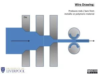
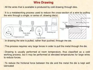
Wire and rod drawing. Variables in Wire Drawing. Various methods of tube drawing. Variation in strain and flow stress. Variation in strain and flow stress in the deformation zone in drawing. Note that the strain increases rapidly toward the exit.

E N D
Variation in strain and flow stress • Variation in strain and flow stress in the deformation zone in drawing. • Note that the strain increases rapidly toward the exit. • When the exit diameter reaches zero, the strain reaches infinity. • Ywire represents the yield stress of the wire.
Wire Drawing/ Rod drawing • s = Ken • (Equation 6.10) • The drawing force then is F = YAfIn (equation 6.62)
Stresses acting on an element in drawing of a cylindrical rod or wire
Die Pressure • Die pressure p at any diameter along the die can be conveniently obtained from p = Yf – s • Yf = flow stress at given point • s = stress applied at that point • (variation in drawing stress and die con…)
Variation in the drawing stress and die contact pressure • Along the deformation zone • As the drawing stress increases the die pressure decreases • Refer to yield criteria
Maximum reduction per pass • s =Y ln = Y, for perfectly plastic materials • thus ln = 1 or = e • = 0.63 • (effect of reduction of cs) (effect of friction factor)
Derive the maximum reduction perpass • For 1- efficiency =0.9 • 2- Power law material • 3- drawing stress with friction
Optimum die angle • Effect of friction factor m and die angle on maximum possible reduction • m = 1 indicates complete sticking • Maximum possible reduction is 63% (Eq. 6.72) • Effect of CS area on the optimum die angle in drawing of copper wire • Increases with reduction
Defects • Seams • Stresses • residual stresses in cold drawing
Residual stresses in cold drawn AISI 1045 carbon steel round • T : transverse • L : longitudinal • R : radial direction
Die angle : 6 - 15º • Sizing pass • Reduction > 45% • Bad surface • Bad lubrication • Initial rod is shaped to a point • Speed 30feet/min to 10000 feet/min • Lubrication • Copper coating • Surface clean • Lubrication oil
Terminology Typical die for drawing round rod or wire Typical wear pattern in wire drawing die
Problem Data: D0 = 10mm Df = 8mm Speed is 0.5 m/s Friction/redundant force 40% Find power and exit die pressure Answer: The true strain in this operation is e1 = ln(102/82) = 0.446
From table 2.3 K = 1300 MPa and n = 0.3 = 1300(0.466)0.30/1.30 = 785 MPa From eq. 6.62 , F = Afln Af = p(0.0082)/4 = 5x10⁻⁵ m2 F = 785* 5x10-5 (0.446) = 0.0175 MN
Power = force x velocity = 0.0175(0.5) = 0.00875 MW =8.75KW Exit Die pressure p = Yf –s Yf being the flow stress of the material at exit Yf = Ken1 = 1300(0.446)0.30 = 1020 MPa s is the drawing stress sd = F/Af = 1.4(0.0175)/0.00005 = 490 MPa • Therefore the die pressure at the exit is p= 1020 – 490 = 530MPa
Relative velocity distribution between roll and strip surfaces • Note the difference in the direction of frictional forces. • The arrows represent the frictional forces acting on the strip.
Where quantity H is defined as At entry f = a; hence H =H0 with f replaced by a. At exit f = 0 hence H = Hf =0
Determination of neutral point • We determine neutral point by simply by equating Entry and Exit Substituting eq. 6.30 into eq. 6.29 we have
Simpler method to find roll force L : arc of contact • we can approximate L as the projected area Dh= hf - ho
Pressure distribution • Function of front and back tension • As tension increases the neutral point shifts and there is reduction in area under the curves
Roll forces: the area under pressure contact length curves multiplied by the strip width
Reduce Pressure Roll force can be reduced by • Smaller radii • Smaller reduction • Higher workpiece temperature • Lower friction • Front and back tension
Calculate power required in rolling Q: A 9 in. wide 6061-O aluminum strip is rolled from a thickness of 1.0 in. to 0.80 in. if the roll radius is 12 in. and the roll rpm is 100, estimate the horse power required for this operation A: The power needed for a set of two rolls is given by eq. 6.42
F is given by eq 6.37 • L is given by eq. 6.36 • Thus L = ((12)(1.0-0.8))1/2 = 1.55 in = 0.13 ft. • w = 9in • For 6061-O Al. K=30000 psi and n=0.2 (table 2.4) • e1 = ln(1.0/0.8) = 0.223
Thus from equation 6.10 , Y= (30000)(0.223)0.2/1.2 = 18500 psi And =1.15(18500) = 21275 psi