Download

1 / 53
590 likes | 957 Vues
Patient Dose Management. L 5a. Are these statements “True” or “False”?. Typically about 40% of radiation entering patient body penetrates through to form X ray image.

E N D
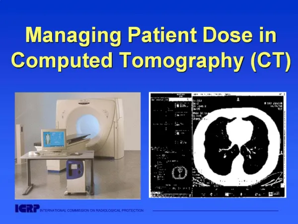
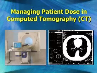
Are these statements “True” or “False”? • Typically about 40% of radiation entering patient body penetrates through to form X ray image. • You are likely to receive more scattered radiation when performing cardiac catheterization for an obese person, compared to one done for a thin person. • During coronary angiography, patient receives more radiation dose in AP (anterior-posterior) projection, compared to LAO cranial angulation. Lecture 5: Patient Dose Management
Educational Objectives • Understand the various factors affecting radiation dose to patient • Understand operator’s role in patient dose management • How to manage patient dose using procedural and equipment factors Lecture 5: Patient Dose Management
determine energy of electrons energy of X-ray photons determine number of electrons number of X ray photons Lecture 5: Patient Dose Management
X-ray tube Photons entering the human body will either penetrate, be absorbed, or produce scattered radiation Lecture 5: Patient Dose Management
To create image some X rays must interact with tissues while others completely penetrate through the patient. (3) Non-uniform beam exits patient, pattern of non-uniformity is the image (2) X rays interact in patient, rendering beam non-uniform (1) Spatially uniform beam enters patient Reproduced with permission from Wagner LK and Archer BR. Minimizing Risks from Fluoroscopic Radiation, R. M. Partnership, Houston, TX 2004. Lecture 5: Patient Dose Management
Image Contrast Object silhouette with no internal details No object image is generated Object image is generated Lecture 5: Patient Dose Management
Detector Dose and Patient Dose X-ray tube • Detector Dose • The total X ray dose, which reaches the detector • Contributes to the image quality, and should therefore be as high as possible. • Significantly lower than the patient dose (~ 1% of patient dose) • Patient Dose • The total X ray dose applied to a patient • Harmful for both the patient and the surrounding staff in scattered radiation. • Therefore, patient dose should be as low as possible Detector dose Patient dose Lecture 5: Patient Dose Management
Because image production requires that beam interact differentially in tissues, beam entering patient must be of much greater intensity than that exiting the patient. Only a small percentage (typically ~1%) penetrate through to create the image. As beam penetrates patient, X rays interact in tissue causing biological changes Beam entering patient typically ~100x more intense than exit beam Reproduced with permission from Wagner LK and Archer BR. Minimizing Risks from Fluoroscopic Radiation, R. M. Partnership, Houston, TX 2004. Lecture 5: Patient Dose Management
Lesson: Entrance skin tissue receives highest dose of x rays and is at greatest risk for injury. Only a small percentage (typically ~1%) penetrates through to create the image. As beam penetrates patient X rays interact in tissue causing biological changes Beam entering patient typically ~100x more intense than exit beam in average size patient Reproduced with permission from Wagner LK and Archer BR. Minimizing Risks from Fluoroscopic Radiation, R. M. Partnership, Houston, TX 2004. Lecture 5: Patient Dose Management
Factors that influence Patient Absorbed Dose • Patient-related factors • Equipment-related factors • Procedure-related factors Lecture 5: Patient Dose Management
Factors that influence Patient Absorbed Dose • Patient-related factors • Patient body weight and habitus Lecture 5: Patient Dose Management
Factors that influence Patient Absorbed Dose • Equipment-related factors • Movement capabilities of C-arm, X ray source, image receptor • Field-of-view size • Collimator position • Beam filtration • Fluoroscopy pulse rate and acquisition frame rate • Fluoroscopy and acquisition input dose rates • Automatic dose-rate control including beam energy management options • X ray photon energy spectra • Software image filters • Preventive maintenance and calibration • Quality control Lecture 5: Patient Dose Management
Procedural-related factors Positioning of image receptor and X ray source relative to the patient Beam orientation and movement Collimation Acquisition and fluoroscopic technique factors on some units Fluoroscopy pulse rate Acquisition frame rate Total fluoroscopy time Total acquisition time Factors that influence Patient Absorbed Dose Lecture 5: Patient Dose Management
Image Handling and Display Image Receptor Automatic Dose Rate Control Operator Patients Electrical Stabilizer Foot Switch X-Ray tube Operator Controls Power Controller High-voltage transformer Primary Controls Generator and Feedback Schematic Lecture 5: Patient Dose Management
Factors that influence Patient Absorbed Dose • Patient-related factors • Patient body weight and habitus Lecture 5: Patient Dose Management
Factors affecting the penetration of radiation through an object Lecture 5: Patient Dose Management
Patient Weight and Habitus Thicker tissue masses absorb more radiation, thus much more radiation must be used to penetrate a large patient. Risk to skin is greater in larger patients! [ESD = Entrance Skin Dose] 15 cm 20 cm 25 cm 30 cm ESD = 1 unit ESD = 2-3 units ESD = 4-6 units ESD = 8-12 units Example: 2 Gy Example: 4-6 Gy Example: 8-12 Gy Example: 16-24 Gy Lecture 5: Patient Dose Management
Tissue Mass and Beam Orientation Thicker tissue masses absorb more radiation, thus much more radiation must be used when steep beam angles are employed. Risk to skin is greater with steeper beam angles! Quiz: what happens when cranial tilt is employed? Lecture 5: Patient Dose Management
40 cm Thick Oblique vs. Thin PA geometry 100 cm Dose rate: 20 – 40 mGyt/min Dose rate: ~250 mGyt/min 80 cm 100 cm 50 cm Lecture 5: Patient Dose Management
Variation in exposure rate with projection anthropomorphic phantom (average-sized) measurements Cusma JACC 1999
Unnecessary body parts in direct radiation field Unnecessary body mass in beam Reproduced with permission from Vañó et al, Brit J Radiol 1998, 71, 510-516 Reproduced from Wagner – Archer, Minimizing Risks from Fluoroscopic X Rays, 3rd ed, Houston, TX, R. M. Partnership, 2000 Lecture 5: Patient Dose Management
Surgical flap At 3 wks At 6.5 mos Following ablation procedure with arm in beam near port and separator cone removed. About 20 minutes of fluoroscopy. Wagner and Archer. Minimizing Risks from Fluoroscopic X Rays. Lecture 5: Patient Dose Management
Big problem! Arm positioning – important and not easy! • Lessons: • Output increases because arm is in beam. • Arm receives intense rate because it is so close to source. Lecture 5: Patient Dose Management
Examples of Injury when Female Breast is Exposed to Direct Beam Reproduced with permission from MacKenzie, Brit J Ca 1965; 19, 1 - 8 Reproduced with permission from Granel et al, Ann Dermatol Venereol 1998; 125; 405 - 407 Reproduced with permission from Vañó, Br J Radiol 1998; 71, 510 - 516. Lecture 5: Patient Dose Management
Lesson • Keep unnecessary body parts, especially arms and female breasts, out of the direct beam. Lecture 5: Patient Dose Management
Factors that influence Patient Absorbed Dose • Equipment-related factors • Movement capabilities of C-arm, X ray source, image receptor • Field-of-view size • Collimator position • Beam filtration • Fluoroscopy pulse rate and acquisition frame rate • Fluoroscopy and acquisition input dose rates • Automatic dose-rate control including beam energy management options • X ray photon energy spectra • Software image filters • Preventive maintenance and calibration • Quality control Lecture 5: Patient Dose Management
Image receptor degrades with time Image Handling and Display Image Receptor Automatic Dose Rate Control Operator Patients Electrical Stabilizer Foot Switch X ray tube Operator Controls Power Controller High-voltage transformer Primary Controls Lecture 5: Patient Dose Management
Image Handling and Display Image Receptor Automatic Dose Rate Control Operator Patients Electrical Stabilizer Foot Switch X ray tube Operator Controls Power Controller High-voltage transformer Primary Controls Feedback circuitry from the image receptor communicates with the X-ray generator modulates X-ray output to achieve appropriate subject penetration by the X-ray beam and image brightness. Lecture 5: Patient Dose Management
Angiography equipment of different FOV (Field of View) Equipment Selection 9-inch (23 cm) 12-inch • dedicated cardiac image intensifier (smaller FOV, 23-25cm) is more dose efficient than a combined cardiac / peripheral (larger FOV) image intensifier • larger image intensifier also limits beam angulation (difficult to obtain deep sagittal angulation ) Lecture 5: Patient Dose Management
Dose rate dependence on image receptor active field-of-view or magnification mode. In general, for image intensifier, the dose rate often INCREASES as the degree of electronic magnification of the image increases. Lecture 5: Patient Dose Management
12" (32 cm) 100 9" (22 cm) 200 6" (16 cm) 300 4.5" (11 cm) 400 RELATIVE PATIENT ENTRANCE DOSE RATE FOR SOME UNITS IMAGE INTENSIFIER Active Field-of-View (FOV) Lecture 5: Patient Dose Management
How input dose rate changes with different FOVs depends on machine design and must be verified by a medical physicist to properly incorporate use into procedures. • A typical rule is to use the least magnification necessary for the procedure, but this does not apply to all machines. Lecture 5: Patient Dose Management
Image Contrast Object silhouette with no internal details No object image is generated Object image is generated Lecture 5: Patient Dose Management
Effect of X ray Beam Penetration on Contrast, Body Penetration, and Dose Lecture 5: Patient Dose Management
In general, every x-ray system produces a range of energies. Higher energy X ray photons higher tissue penetration. Beam energy: High energy X rays: poor contrast and low skin dose Low energy X rays: high image contrast but high skin dose Middle energy X rays: high contrast for iodine and moderate skin dose Lecture 5: Patient Dose Management
The goal is to shape the beam energy spectrum for the best contrast at the lowest dose. An improved spectrum with 0.2 mm Copper filtration is depicted by the dashes: Beam energy: Low-contrast high energy X rays are reduced by lower kVp Filtration reduces poorly penetrating low energy X rays Middle energy X rays are retained for best compromise on image quality and dose Lecture 5: Patient Dose Management
kVp (kiloVolt-peak) Beam energy: kVp controls the high-energy end of the spectrum and is usually adjusted by the system according to patient size and imaging needs: Reproduced with permission from Wagner LK, Houston, TX 2004. Lecture 5: Patient Dose Management
Comparison of Photon Energy Spectra Produced at Different kVp Values Lecture 5: Patient Dose Management (from The Physical Principles of Medical Imagings, 2Ed, Perry Sprawls)
Filtration Beam energy: Filtration controls the low-energy end of the spectrum. Some systems have a fixed filter that is not adjustable; others have a set of filters that are used under differing imaging schemes. Reproduced with permission from Wagner LK, Houston, TX 2004. Lecture 5: Patient Dose Management
Filter Lecture 5: Patient Dose Management
Filtration – possible disadvantage (1) Advantages -- they can reduce skin dose by a factor of > 2. (2)Disadvantages -- they reduce overall beam intensity and require heavy-duty X ray tubes to produce sufficient radiation outputs that can adequately penetrate the filters. Filters: Beam energy spectrum before and after adding 0.2 mm of Cu filtration. Note the reduced intensity and change in energies. To regain intensity tube current must increase, requiring special x-ray tube. Lecture 5: Patient Dose Management
Filtration –potential disadvantage If filters reduce intensity excessively, image quality is compromised, usually in the form of increased motion blurring or excessive quantum mottle (image noise). Lesson: To use filters optimally, systems must be designed to produce appropriate beam intensities with variable filter options that depend on patient size and the imaging task. Lecture 5: Patient Dose Management
Dose vs. Noise 15 µR per frame 24 µR per frame 2 µR per frame Lecture 5: Patient Dose Management
Efficient Dose and Image Quality Management 0.2 mm Cu-eq MRC No Cu-eq Conventional 0.5 mm Cu-eq MRC -50% Same Image quality • Achieving significant patient pose savings and yet keeping image quality at the same level 14 Patient Dose[cGY/min] 10 6 2 30cm water 0.25 0.5 0.75 1 Detector Dose[GY/s] Lecture 5: Patient Dose Management