Download
1 / 5
50 likes | 75 Vues
The low maintenance and robustness induction motors have many applications in the industries. The speed control of induction motor is more important to achieve maximum torque and efficiency. Various speed control techniques like, Direct Torque Control, Sensorless Vector Control and Field Oriented Control. Soft computing technique the Fuzzy logic is applied in this work .We have carried on with the hardware implementation for speed control of induction motor using the fuzzy logic control . Using the arduino micro controller, we have developed a hardware setup which is able to control the speed of induction motor by using Arduino Uno .We can conclude that we have been able to get a good control over the speed of motor. Talat Jabeen | Ganesh Wakte "Design and Implementation of Speed Control of Induction Motor using Arduino Based FLC" Published in International Journal of Trend in Scientific Research and Development (ijtsrd), ISSN: 2456-6470, Volume-3 | Issue-4 , June 2019, URL: https://www.ijtsrd.com/papers/ijtsrd23684.pdf Paper URL: https://www.ijtsrd.com/engineering/electrical-engineering/23684/design-and-implementation-of-speed-control-of-induction-motor-using-arduino-based-flc/talat-jabeen<br>

E N D
International Journal of Trend in Scientific Research and Development (IJTSRD) Volume: 3 | Issue: 4 | May-Jun 2019 Available Online: www.ijtsrd.com e-ISSN: 2456 - 6470 Design and Implementation of Speed Control of Induction Motor using Arduino Based FLC Talat Jabeen1, Ganesh Wakte2 1Student, 2Professor, 1,2Integrated Power System, 1,2Tulsiramji Gaikwad Patil College of Engineering & Technology, Nagpur, Maharashtra, India How to cite this paper: Talat Jabeen | Ganesh Wakte Implementation of Speed Control of Induction Motor using Arduino Based FLC" Published in International Journal of Trend in Scientific Research and Development (ijtsrd), ISSN: 2456- 6470, Volume-3 | Issue-4, June 2019, pp.328-332, URL: https://www.ijtsrd.c om/papers/ijtsrd23 684.pdf Copyright © 2019 by author(s) and International Journal of Trend in Scientific Research and Development Journal. This is an Open Access article distributed under the terms of the Creative Commons Attribution License (CC BY 4.0) (http://creativecommons.org/licenses/ by/4.0) 3.linear control shows good performance only at one operating speed 4.The coefficients must be chosen properly for acceptable results, but choosing the proper coefficient with varying parameters like set point is very difficult To implement conventional control, the model of the controlled system it must be known. The usual method of computation of mathematical model of a system is difficult. When there are system parameter variations or environmental disturbance, the behavior of the system is not satisfactory. Usually classical control is used in electrical motor drives. The classical controller designed for high performance increases the complexity of the design and hence the cost. Advanced control based on artificial intelligence technique is called intelligent control. Every system with artificial intelligence is called self-organizing system. Earlier the production of electronic circuits and microprocessors with high computation ability and operating speed has grown very fast. The high power, high speed and low cost modern processors like DSP, FPGA and ASIC IC’s along with power technique switches IGBT made the intelligent control to be used widely in electrical drives. Intelligent control, act better than conventional adaptive controls. Artificial intelligent techniques divide two groups: hard computation and soft computation. Expert system ABSTRACT The low maintenance and robustness induction motors have many applications in the industries. The speed control of induction motor is more important to achieve maximum torque and efficiency. Various speed control techniques like, Direct Torque Control, Sensorless Vector Control and Field Oriented Control. Soft computing technique – the Fuzzy logic is applied in this work .We have carried on with the hardware implementation for speed control of induction motor using the fuzzy logic control . Using the arduino micro controller, we have developed a hardware setup which is able to control the speed of induction motor by using Arduino Uno .We can conclude that we have been able to get a good control over the speed of motor. Keywords: Speed, Arudino Uno, Induction motor, Field Oriented Control, Fuzzy logic controller, Maximum torque, Membership function, Induction motor INTRODUCTION It is not possible Induction motors are being applied today to wider range of applications requiring variable speed. Generally, Variable speed drives for Induction Motor (IM) require both wide operating range of speed and fast torque response, regardless of load variations. This leads to more advanced control methods to meet the real demand. The conventional control methods have the following difficulties 1.depends on the accuracy of the mathematical model of the systems 2.The expected performance is not met due to the output disturbance, motor saturation and thermal variations "Design and IJTSRD23684 belongs to hard computation techniques which has been the first artificial intelligent technique. In recent two decades, soft computation is used widely in electrical drives. They are, 1.Artificial Neural Network (ANN) 2.Fuzzy Logic Set (FLS) 3.Fuzzy-Neural Network (FNN) 4.Genetic Algorithm Based system (GAB) 5.Genetic Algorithm Assisted system (GAA) ANN and FLS technique are quite different, and yet with unique capabilities useful in information processing by specifying mathematical relationships, numerous variables in a complex system, performing mappings with degree of imprecision, control of nonlinear system to a degree not possible with conventional linear systems. It is a technique to embody human-like thinking into control system. This controller can be designed to emulate human deductive thinking, that is, the process people use to infer conclusions from what they know. Fuzzy control has been primarily applied to the control of processes through fuzzy linguistic descriptions. Fuzzy control system consists of four blocks as shown in Fig. 1. @ IJTSRD | Unique Paper ID - IJTSRD23684 | Volume – 3 | Issue – 4 | May-Jun 2019 Page: 328
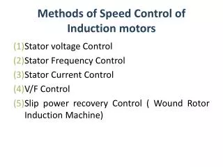
International Journal of Trend in Scientific Research and Development (IJTSRD) @ www.ijtsrd.com eISSN: 2456-6470 utilizing apace vector modulation, predictive control, and dead beat control. All of these techniques increase the complexity of the drive systems. B.Sensorless Vector Control The sensorless control method is valid for both high and low speed range. Using the traditional method, the stator terminal voltages and currents estimate the rotor angular speed, slip angular speed and the rotor flux. In this case, around zero speed, the slip angular velocity estimation becomes impossible since division by zero takes place. Another strategy is, as short sampling time is assumed, we could solve the linearized differential equations, then get an algebraic equation for the estimation of rotor parameters. The problem of achieving high dynamic performance in AC motor drives without the need for a shaft position/speed sensor has been under study widely. The advantages of speed sensorless operation of the drives are lower cost, reduced size of the drive machines, elimination of the sensor cable and increased capability. The zero rotor speed problem persisting in the sensorless speed control scheme was resolved sacrificing the dynamic and steady state performance. Figure1. Fuzzy Control System The paper deals about the hardware implementation of fuzzy logic in the speed control of Induction motor. Various control techniques are discussed in Section II. The Section III discusses the induction Motor. Section IV describes the Fuzzy logic controller. Section. V describes the hardware implementation of the fuzzy logic based induction motor controller followed by conclusion in Section VI. VARIOUSCONTROLTECHNIQUES Because of advances in power electronic switches and microprocessors, variable speed drive system using various control technique have been widely used in many applications, namely Field oriented control or vector control, Direct torque control, Sensorless vector control. A.Direct Toque Control Direct Torque Control (DTC) scheme is very simple. In its basic configuration it consists of DTC controller, torque and flux calculator and VSI. In principle, the DTC method selects one of the inverter’s six voltage vectors and two zero vectors in order to keep the stator flux and torque within a hysteresis band around the demand flux and torque magnitudes. The torque produced by the induction motor can be expressed as shown below 2.1 Figure 2.1 Applied Voltage Vector This shows the torque produced is dependent on the stator flux magnitude, rotor flux magnitude and the phase angle between the stator and rotor flux vectors. The induction motor stator equation is given by 2.2 Can be approximated as shown below over a short time period if the stator resistance is ignored, then 2.3 This means that the applied voltage vector as shown in the Fig. 2 determines the change in the stator flux vector as shown in Fig. 3. If a voltage vector is applied that changes stator flux to increase the phase angle between the stator flux and rotor flux vectors, then the torque produced will also increase. Two problems are usually associated with DTC drives which are based on hysteresis comparators are: 1.Variable switching frequency due to hysteresis comparators used for the torque and flux estimators 2.Inaccurate stator flux estimations which can degrade the drive performance, some schemes have managed to maintain an average constant switching frequency by Figure 2.2 Stator Flux Vector C.Field Oriented Control Field oriented control (FOC) technique is intended to control the motor flux, and thereby be able to decompose the AC motor current into “flux producing” and “torque producing” components. These current components can be treated separately, and then recombined to create the actual motor phase currents. This gives a solution to the boost adjustment problem, and also provides much better control of the motor @ IJTSRD | Unique Paper ID - IJTSRD23684 | Volume – 3 | Issue – 4 | May-Jun 2019 Page: 329
International Journal of Trend in Scientific Research and Development (IJTSRD) @ www.ijtsrd.com eISSN: 2456-6470 torque, which allows higher dynamic performance. Some approaches which yield the maximum torque have been published. Xu and Novotny [3] insisted that a method which set the stator flux reference inversely proportional to the rotor speed should produce more output torque than a conventional method, which set the rotor flux reference inversely proportional to the rotor speed. However, in their method, there exist some speed ranges where the maximum torque cannot be obtained. Kim and Sul suggested a voltage control strategy for the maximum torque operation of induction motors in the field weakening region, considering the voltage and current constraints. However this approach neglects the stator resistor for the analysis. Wallace and Novotny [4] suggested an instantaneous maximum-torque generation method for induction motors. In this approach, the entire current input is used for generating the rotor flux before the torque is developed. Then, at the moment that the rotor flux reaches the steady state value, the entire input current is switched to produce torque current component. INDUCTION MOTOR To accomplish field oriented control, the controller needs to have an accurate “model” of the induction motor. Over the last several years a large number of different schemes have been proposed to accomplish the “flux and torque control” desired. Many of the today’s technique involve some sort of self tuning at startup in order to obtain information which helps to design accurate model of the motor to produce more optimal control. In addition, there are also techniques by which the models can adaptively adjust to changing conditions such as the motor temperature going from cold to warm which will have an impact of slip. The output equations of the induction motors can be expressed in the synchronously rotating d-q reference frame as follows [19]. 3.7 3.8 And Vqs , Vds ,q- and d- axes stator voltages; iqs , ids , q- and d- axes stator currents; Rs , Rr stator and rotor resistances; φqr ,φdr , q- and d- axes rotor fluxes; ωr rotor speed; ωe synchronous speed. The generating torque of the induction motor is 3.9 where, P = pole number; Lm = mutual inductance; Lr = rotor inductance; From the above the continuous- time model of the induction motors, a discrete-time model can be derived with the following assumptions 1.The sampling time is sufficiently small enough to achieve a good approximation of a continuous-tim. 2.Since the mechanical time constant is much larger than the electrical one, rotor speed is assumed to be constant during the sampling period. 3.input voltages, Stator currents and rotor flux are also considered constant during the sampling period. Using the above assumptions, a discrete-time model of induction motors can be expressed as 3.1 Where, 3.2 3.10 3.3 Where 3.11 3.4 3.12 T sampling time The discrete model is used in the simulation. Maximum torque generation 3.5 Maximize 3.13 Under constraints 3.6 3.14 @ IJTSRD | Unique Paper ID - IJTSRD23684 | Volume – 3 | Issue – 4 | May-Jun 2019 Page: 330
International Journal of Trend in Scientific Research and Development (IJTSRD) @ www.ijtsrd.com eISSN: 2456-6470 3.15 where, 3.16 3.17 3.18 FUZZY LOGIC CONTROLLER To obtain fuzzy based model of the motor, the training system derives information from two main sources, a. The static flux linkage curves of the motor, which provides important information about the electromagnetic characteristics of the motor b. The dynamic real time operating waveforms of the motor, which can include real-time operating effects, such as mutual coupling between phases, temperature variations, eddy currents and skin effects. During the training phase, each input-output data pair, which consists of a crisp numerical value of measured flux linkage, current, angle and voltage is used to generate the fuzzy rules. To determine a fuzzy rule from each input-output data pair, the first step is to find the degree of each data value in every membership region. The variable is assigned to the region with the maximum degree. When each new rule is generated from the input-output data pairs, a rule degree or truth is assigned to that rule, where this rule degree is defined as the degree of confidence that the rule does in fact correlate to the function relating voltage and current to angle. In the developed method a degree is assigned which is the product of the membership function degree of each variable in its respective region. Every training data set produces a corresponding fuzzy rule that is stored in the fuzzy rule base. Therefore, as each input output data pair is processed, rules are generated. A fuzzy rule or knowledge base is in the form of two dimensional table,Speed error is calculated with comparison between reference speed and speed signal feedback. Speed error and speed error changing are fuzzy controller inputs. Input variables are normalized with a range of membership functions specified and the normalization factors are named as K1 and K2. Suitable normalization has direct influence in algorithm optimality and faster response. Fig. 4.1 shows normalized membership functions for input and output variables. A fuzzy logic controller operation is based on the rules formed. (4b) (4c) Figure -4 (a) Membership function for input variable K1 (b) Membership function for input variable K2 (c) Membership function for output variable RESULTS Fuzzy Controller results: Input variables are required to be normalized with ranges of membership functions specified. Suitable normalization has direct influence in algorithm and results in optimality and faster response. The fuzzy logic controller operation is based on the control operation shown in Table I. TABLE I Figure 5.1 the Block Diagram (4a) @ IJTSRD | Unique Paper ID - IJTSRD23684 | Volume – 3 | Issue – 4 | May-Jun 2019 Page: 331
International Journal of Trend in Scientific Research and Development (IJTSRD) @ www.ijtsrd.com eISSN: 2456-6470 The supply from the mains is given to the potential and the current transformer which measures the voltage and the current. This voltage and current is applied through the precision rectifiers to the controller which is Arduino Uno. The microcontroller uses this voltage and current to generate PWM pulses . These PWM pulses are used to drive the H- Bridge which drives the induction motor. The fuzzy logic controller provides the controlling scheme through the microcontroller which helps in controlling the speed of the motor. region,” IEEE Trans. Ind. Applicat., vol. 28, pp. 1353– 1358, Nov. /Dec. 1992. [4]D. W. Novotny and T. A. Lipo. Vector Control and Dynamics of AC Drives, Oxford University Press, 1997. [5]T. G. Habetler et al., “Direct torque control of induction machines using space vector modulation,” IEEE Trans. Ind. Applicat., vol. 28,pp. 1045–1053, Sept./Oct. 1992. [6]I. Takahashi and T. Noguchi. A new quick response and high efficiency control strategy for an induction motor. IEEE Trans. Industry Applications. Vol. IA-22, No. 5, pp. 820-827, Sept/Oct 1986. [7]F. D. S. Cardoso, J. F. Martins, V. F. Pires, "A Comparative Study of a PI, Neural Network and Fuzzy Genetic Approach Controllers for an AC Drive" 5th International Workshop on Advanced Motion Control, pp.375 –380, 29 Jun 1998. [8]A. Munoz-Garcia, T.A.Lipo, D.W.Novotny, "A New Iinduction Motor V/f Control Method Capable of High- Performance Regulation at Low Speeds “, IEEE Transactions On Industry Application, Vol.34, pp.813 - 821, July-Aug.1998. [9]B. K. Bose, "Intelligent Control and Estimation in Power Electronics and Drives" IEEE International Electric Machines and Drives Conference Record, pp. TA2/2.1 - TA2/2.6, May 1997. [10]C. Y. Won and B. K. Bose, "An Induction Motor Servo System with Improved Sliding Mode Control”, IEEE Conf.Rec.of IECON’92, pp.60-66, 1992.M. Young, The Technical Writer’s CA:University Science, 1989. Handbook. Mill Valley, Figure 5.2 the Implemented Module CONCLUSION Thus we conclude that we have been able to present a hardware implementation of speed control of induction motor using the fuzzy logic control . Using the Arduino Uno micro controller we have developed a hardware setup which is able to control the speed of induction motor .The fuzzy logic controller along with the microcontroller, the PWM pulse and the H-Bridge together controls the speed of the induction . This scheme can be used to drive the motor at the desired speed. We also conclude that in future which necessary modification this scheme can be implemented for various other motors and the system can be escalated to work through an Android app as well as it can be controlled through the cloud. REFERENCES [1]S. H. Kim and S. K. Sul, “Voltage control strategy for maximum torque operation of an induction machine in the field weakening region,” in Proc. IECON’94, 1994, pp. 599–604. [11]Maiti, S. (2008). Model Reference Adaptive Controller Based Rotor Resistance and Speed Estimation Techniques for Vector Induction Motor Drive Utilizing Reactive Power, IEEE Trans on Industry Electronics Vol. 55, pp. 594-601. [12]Sen, P.C. (1990). Electric Motor Drives and Control Past, Present and Future, IEEE transactions on Industrial Electronics, vol. 37, no. 6, pp. 562-575. [13]Bose, B. K. (2002). Present day Power Electronics and AC Drivers, Prentice Hall. [14]Ho, E.Y.Y. and Sen, P.C. (1988). Decoupling Control of Induction Motor Driver, IEEE Transactions on Industrial Electronics, vol. 35, no. 2, pp. 253-262. [15]Santisteban, J. A. and Stephan, R.M., Vector Control Methods for Induction Machines: An Overview, IEEE Transactions on Education, vol. 44, no. 2. [16]Novotny, D.W. and Lorenz, R.D. (1986). Prologue to Field Orientation and High Performance AC Drives, IEEE Tutorial Course Notes. [17]Blaschke, F. (1971). A New Method for the Structural Decoupling of AC Induction Machines, Conf. Rec. IFAC. [2]B. K. Bose, Power Electronics and AC Drives. Englewood Cliffs, NJ:Prentice Hall, 1986. [18]Yoo, B. and Ham, W. (1998). Versatile fluffy sliding mode control of nonlinear framework, IEEE Transactions on Fuzzy Systems, ol. [3]X. Xu and D. W. Novotny, “Selecting the flux reference for induction machine drives in the field weakening @ IJTSRD | Unique Paper ID - IJTSRD23684 | Volume – 3 | Issue – 4 | May-Jun 2019 Page: 332