Download
1 / 5
50 likes | 56 Vues
The purpose of this paper is for the students to know the basic function of main components of refrigeration system. Theoretical and experimental of design calculation of main components and their results are reported in this paper. During the performance of testing, the length of expansion device is varied and the result data are also described. In this system, R134a refrigerant is used as working substance. Because it is now being used for a replacement of R 12 CFC refrigerant. It can be handled safely because it is not toxic, corrosive and flammable. Moreover, it has no damage effect to ozone layer and greenhouse. Ko Ko | Aye Aye San | Khin Maung Than "Design Calculation of Main Components for Lab Based Refrigeration System" Published in International Journal of Trend in Scientific Research and Development (ijtsrd), ISSN: 2456-6470, Volume-3 | Issue-6 , October 2019, URL: https://www.ijtsrd.com/papers/ijtsrd29212.pdf Paper URL: https://www.ijtsrd.com/engineering/mechanical-engineering/29212/design-calculation-of-main-components-for-lab-based-refrigeration-system/ko-ko

E N D
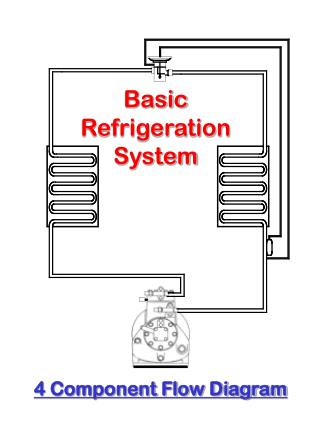
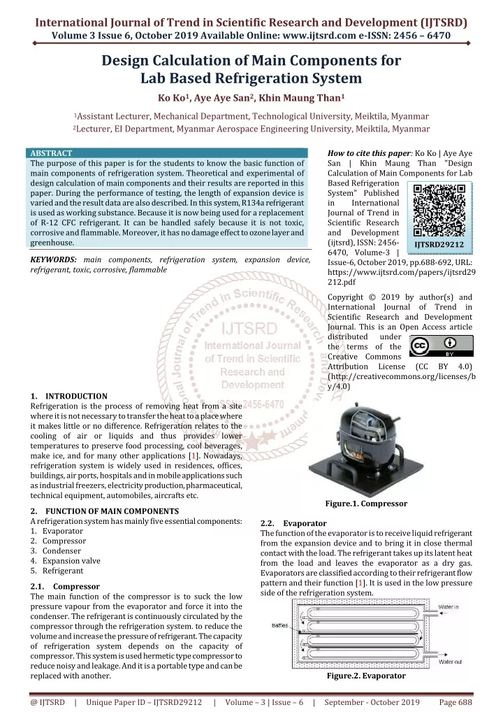
International Journal of Trend in Scientific Research and Development (IJTSRD) Volume 3 Issue 6, October 2019 Available Online: www.ijtsrd.com e-ISSN: 2456 – 6470 Design Calculation of Main Components for Lab Based Refrigeration System Ko Ko1, Aye Aye San2, Khin Maung Than1 1Assistant Lecturer, Mechanical Department, Technological University, Meiktila, Myanmar 2Lecturer, EI Department, Myanmar Aerospace Engineering University, Meiktila, Myanmar ABSTRACT The purpose of this paper is for the students to know the basic function of main components of refrigeration system. Theoretical and experimental of design calculation of main components and their results are reported in this paper. During the performance of testing, the length of expansion device is varied and the result data are also described. In this system, R134a refrigerant is used as working substance. Because it is now being used for a replacement of R-12 CFC refrigerant. It can be handled safely because it is not toxic, corrosive and flammable. Moreover, it has no damage effect to ozone layer and greenhouse. KEYWORDS: main components, refrigeration system, expansion device, refrigerant, toxic, corrosive, flammable How to cite this paper: Ko Ko | Aye Aye San | Khin Maung Than "Design Calculation of Main Components for Lab Based Refrigeration System" Published in International Journal of Trend in Scientific Research and Development (ijtsrd), ISSN: 2456- 6470, Volume-3 | Issue-6, October 2019, pp.688-692, URL: https://www.ijtsrd.com/papers/ijtsrd29 212.pdf Copyright © 2019 by author(s) and International Journal of Trend in Scientific Research and Development Journal. This is an Open Access article distributed under the terms of the Creative Commons Attribution License (http://creativecommons.org/licenses/b y/4.0) IJTSRD29212 (CC BY 4.0) 1.INTRODUCTION Refrigeration is the process of removing heat from a site where it is not necessary to transfer the heat to a place where it makes little or no difference. Refrigeration relates to the cooling of air or liquids and thus provides lower temperatures to preserve food processing, cool beverages, make ice, and for many other applications [1]. Nowadays, refrigeration system is widely used in residences, offices, buildings, air ports, hospitals and in mobile applications such as industrial freezers, electricity production, pharmaceutical, technical equipment, automobiles, aircrafts etc. 2.FUNCTION OF MAIN COMPONENTS A refrigeration system has mainly five essential components: 1.Evaporator 2.Compressor 3.Condenser 4.Expansion valve 5.Refrigerant 2.1.Compressor The main function of the compressor is to suck the low pressure vapour from the evaporator and force it into the condenser. The refrigerant is continuously circulated by the compressor through the refrigeration system. to reduce the volume and increase the pressure of refrigerant. The capacity of refrigeration system depends on the capacity of compressor. This system is used hermetic type compressor to reduce noisy and leakage. And it is a portable type and can be replaced with another. Figure.1. Compressor 2.2.Evaporator The function of the evaporator is to receive liquid refrigerant from the expansion device and to bring it in close thermal contact with the load. The refrigerant takes up its latent heat from the load and leaves the evaporator as a dry gas. Evaporators are classified according to their refrigerant flow pattern and their function [1]. It is used in the low pressure side of the refrigeration system. Figure.2. Evaporator @ IJTSRD | Unique Paper ID – IJTSRD29212 | Volume – 3 | Issue – 6 | September - October 2019 Page 688
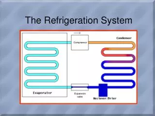
International Journal of Trend in Scientific Research and Development (IJTSRD) @ www.ijtsrd.com eISSN: 2456-6470 2.3.Condenser The purpose of the condenser is to remove the hot, high- pressure gas or vapor refrigerant from the compressor and cool it to remove first the superheat and then the latent heat, so that the refrigerant will condense back to a liquid. In nearly all cases, the cooling medium will be air or water or combination of the two[1]. As condenser is one of an important device for the refrigeration system, it is used in the high pressure side of the refrigeration system. 3.LAYOUT OF LAB BASED REFRIGERATION SYSTEM Figure.5. Lab based refrigeration system The design and construction of all components for lab based refrigeration system is as shown in Figure 5. It is a kind of domestic refrigerator. All components are fixed firmly on the stand board. The testing results are based on different lengths of capillary tube. The lengths of capillary tube were 0.9144 m, 1.524 m and 2.135 m. Because this lab based refrigeration system was only the project. We observed that during the testing, suction pressure, discharge pressure and others are changed. Running time is 15 minutes. The components of this system are; A.Compressor B.Condenser C.Evaporator D.Expansion device E.High pressure gauge F.Low pressure gauge G.Filter drier H.Sight glass I. Shutoff valves 4.DESIGN SPECIFICATIONS OF MAIN COMPONENTS 4.1.Detail Designs of Compressor For the volumetric efficiency of compressor, 1 γ 2 v 1 P Where, η = volumetric efficiency 1 P= suction pressure, Pa 2 P = delivery pressure, Pa c = clearance (between 2% and 5%) γ= Isentropic index For piston diameter and stroke length, 2 πD P = ×L×N×n 4 Where, N = compressor speed, rpm n = no. of piston P = Piston displacement, cm3/rev L = 0.8D (Hermetic type compressor) Figure.3. Condenser 2.4.Expansion Device It is also known as a metering device. The main performance of the expansion device is to control the flow of sufficient pressure differential between the high and low pressure sides of the system. It is used for metering the correct amount of refrigerant to the load on the evaporator [2]. Figure.4. Expansion device 2.5 Refrigerant The refrigerant is usually a liquid or gaseous compound. It easily absorbs heat from the fluid medium and can provide cooling or air conditioning in combination with other components such as compressors and evaporators. Without refrigerant, there would be no air conditioning and refrigeration technology. P η = 1 + c - c (1) v (2) D D Figure.5. Refrigerant @ IJTSRD | Unique Paper ID – IJTSRD29212 | Volume – 3 | Issue – 6 | September - October 2019 Page 689
International Journal of Trend in Scientific Research and Development (IJTSRD) @ www.ijtsrd.com eISSN: 2456-6470 For required work done of compressor, − P 1 γ For Log mean temperature difference, T -T ∆T = T ln T Where, T = maximum temperature difference, °C T = minimum temperature difference, °C ∆T = log mean temperature difference, °C For the capacity of evaporator, Q = U ×A ×∆T Where, Q = capacity of evaporator, W U = overall heat transfer coefficient, W/m2K A = area of the evaporator, m2 For the length of evaporator tube, L πD A × = Where, L = length of the evaporator tube, m D = outside diameter of evaporator, m For overall heat transfer coefficient of evaporator, 1 U + + − γ 1 γ d1 d2 (9) P γ m = − 2 W P V 1 (3) c 1 1 d1 1 d2 Where, W= work done of compressor, kJ/cycle For the required actual power of compressor, N W P = c d1 d2 c× m (4) 60 Where, P = actual input power, kW For input power of compressor, (10) eva eva eva m eva W c Input power = (5) eva η mech eva Where, η W 4.2.Heat Transfer in Condenser For heat transfer in condenser, con Q = copper U × A Where, = con Q heat rejected in condenser, W U = overall heat transfer coefficient of air velocity, (60-65 W/m2K) A = area of condenser, m2 Foe mean temperature of the condenser, ( ( ( r a,out T - T Where, r T = condensing temperature, °C T = air inlet temperature, °C T = air outlet temperature, °C For heat transfer area of the condenser, L πd A × = Where, t d = outside diameter of condenser, m L = length of the condenser, m 4.3.Detail Designs of Evaporator Ta= ambient temperature = 306 K T1= evaporator outlet temperature = 263 K Te= evaporator temperature = 245 K = mechanical efficiency = input power of compressor, W (11) mech eva eva eva input eva eva ∆T × (6) con m = (12) eva x 1 1 a h k h copper r a i Where, r h = heat transfer coefficient of refrigerant, W/m2 i h = heat transfer coefficient of air side, W/m2K x = thickness of evaporator, °C k = thermal conductivity of aluminum, W/mK Air side heat transfer coefficient can be calculated the following equation, 1 ∆T 1.24 h Where, ∆T = sub cooling temperature difference, °C For modified latent heat transfer coefficient, 3 h =h + c ∆T 8 Where, h = latent heat, kJ/kg h = modified latent heat, kJ/kg con ) ( - T - T T - T ) T - T r a,in r a,out a ∆T = (7) ) ) m a r a,in ln 3 = i (13) i D a,in a, out i (8) con t con (14) fg1 fg f con fg fg1 fc = correction factor @ IJTSRD | Unique Paper ID – IJTSRD29212 | Volume – 3 | Issue – 6 | September - October 2019 Page 690
International Journal of Trend in Scientific Research and Development (IJTSRD) @ www.ijtsrd.com eISSN: 2456-6470 For heat transfer coefficient of refrigerant, ( r r µ Where, f k = thermal conductivity of refrigerant, W/mK r ρ = density of refrigerant, kg/m3 ρ = density of gas, kg/m3 g = gravitational force, m/s µ= viscosity of refrigerant, kg/ms 4.4.Expansion Device Inside diameter = 0.5 mm to 2.25 mm Length = 0.5 mm to 5 m 5.RESULTS AND DISCUSSIONS 5.1.Design Calculation for Compressor P1= 96.5 kPa P2= 2413 kPa c = 2% γ = 1.14 By using Equation (1), Volumetric efficiency of compressor is ηv= 68 % By using Equation (2), No. of piston, n = 1 Compressor speed, N = 3000 rpm (2 poles compressor motor) L = 0.8D (Hermetic compressors) Piston displacement is P = 9.2 cm3/rev Piston diameter, D = 24 mm Piston stroke length, L = 19 mm By using Equation (3), V1= 9.2 cm3/rev γ = 1.14 (isentropic compression) Required work done of compressor is W= 3.5047 ×10⁻³ kJ/cycle By using Equation (4), Actual power to drive the compressor, P = 0.1752 kW By using Equation (5), η = 0.92 Input power of compressor, W = 3.809×10⁻³kW 5.2.Design Calculation of Condenser t d = 0.004 m r T = 65°C T = 32°C 5.4.Selection of Expansion Device Capillary tube is one of the important types of used in expansion device. The selection of capillary depends on the compressor work done. Due to the testing results, capillary tube length is inversely proportional to the refrigerant flows. And then, condenser U By using Equation (7), Mean temperature difference is ∆T = 27.6°C By using Equation (6), Q = 323 W Area of condenser is A = 0.195 m2 By using Equation (8), Length of condenser is L = 15.5 m 5.3.Design Calculation of Evaporator T = T = o T = 43 K By using Equation (9), Log mean temperature difference, By using Equation (13), Inside diameter of evaporator, 2t D D − = Di = 0.00635 − (2 ×0.00068) = 0.005 m Heat transfer coefficient of air side is i h = 26.36 W/m2 By using Equation (14), fc = 0.065 h = 215 kJ/kg ( Heat transfer coefficient for refrigerant side is h = 216.49 kJ/kg By using Equation (15), r ρ = 1379.8 kg/m3 ρ = 4.833 kg/m3 = 60 W/m2K copper 1 ) × 3 r × − × × g k h ρ ρ ρ 4 r g fg1 = h 0.555 (15) ÷ ∆T D i i m con con g con a T − a T − e T = 61 K d1 d2 ∆T = 51.47 K m i eva eva rP = 0.9 MPa) fg D fg1 g r k = 104.5 × 10⁻³ W/mK µ= 0.0392 × 10⁻⁴ N/m2 Heat transfer coefficient of refrigerant is r h = 44.324 W/m2 By using Equation (12), Q = 323 W Overall heat transfer coefficient of evaporator is U = 23.95 W/m2K By using Equation (10), Area of evaporator is A = 0.2996 m2 By using Equation (11) Length of the evaporator tube is L = 15.02 m c eva mech eva input eva a,in eva @ IJTSRD | Unique Paper ID – IJTSRD29212 | Volume – 3 | Issue – 6 | September - October 2019 Page 691
International Journal of Trend in Scientific Research and Development (IJTSRD) @ www.ijtsrd.com eISSN: 2456-6470 pressure and evaporator pressure are increased. According to the experiment, the suitable length of the capillary tube is between 1.524 m and 4.877 m. Table1. Refrigeration Preference Chart for Capillary Tubing (Fan Cooled Units Only and add 10 % length for Static Cooled) R-134a/R-401a/R-401b Low Medium ° ° ° °C m ° ° ° °C 1/8 26 3.073 26 2.337 26 1.346 1/6 26 1.198 26 2.692 26 2.007 1/5 31 1.499 31 0.991 31 0.660 ¼ 31 1.194 31 2.515 31 1.676 1/3 42 2.591 42 According to above table, the selection for capillary tube length is 1.524 m. Table2. Results for Main Components of Lab Based Refrigeration System No. Main Components 1 Compressor 2 Compressor 3 Piston diameter 4 Stroke length 5 Condenser length 6 Condensing pressure 7 Condensing temperature 8 Evaporator length 9 Evaporating pressure 10 Evaporating temperature 11 Capillary tube length High H.P ° ° ° °C m m 2 42 0.991 Value 3000 0.175 0.024 0.019 15.5 2413 42 15.02 0.0965 -28 1.524 0.0008 ID 0.0002 OD Unit rpm kW m m m MPa °C m MPa °C m 12 Capillary tube diameter m Table3. Performance Testing and Results for Capillary Tube Length of 0.9144 m Time (min) Suction Discharge Inlet 0-5 18 365 8.3 5-10 20 365 1 10-15 20 365 0 Evaporator Temp. (° ° ° °C) Condenser Temp. (° ° ° °C) Outlet 18 13 10 Pressure (psi) Inlet 41.2 42.7 44.7 Outlet 31.2 32.7 34.7 Table4. Performance Testing and Results for Capillary Tube Length of 1.524 m Time (min) Suction Discharge Inlet 0-5 12 345 17 5-10 12 345 8.1 10-15 14 350 5 Evaporator Temp. (° ° ° °C) Condenser Temp. (° ° ° °C) Outlet 26 25 23 Pressure (psi) Inlet 38.5 35.9 25.9 Outlet 28.5 25.9 15.9 Table5. Performance Testing and Results for Capillary Tube Length of 2.134 m Time (min) Suction Discharge Inlet 0-5 13 360 15 5-10 15 370 7.9 10-15 16 375 5 Evaporator Temp. (° ° ° °C) Condenser Temp. (° ° ° °C) Outlet 26 23 21 Pressure (psi) Inlet 32.9 37.5 42 Outlet 22.9 27.5 32 6.CONCLUSION This lab based refrigeration system analyzed the detail designs of compressor, condenser, evaporator and coefficient of performance by varying the capillary tube length. This system is simple in structure and easy to maintain. It can be used for laboratory experiments of basic refrigeration processes and principles of each component. It is fairly inexpensive and therefore much suitable for mechanical engineering students. It can also be used as teaching aids. The design calculations and results will help for other new designs. 7.RRFERENCES [1]G. F. Hundy, A. R. Trott and T. C. Welch:"Refrigeration and Air-Conditioning", Fourth Edition, (2008) [2]William C. Whitman, William M. Johnson, John A. Tomczyk, Eugene Silberstein: "Refrigeration & Air Conditioning Technology", Seventh Edition, (2013) @ IJTSRD | Unique Paper ID – IJTSRD29212 | Volume – 3 | Issue – 6 | September - October 2019 Page 692