Download
1 / 3
30 likes | 40 Vues
This paper provides to design penstock and nozzle for 5kW Pelton turbine micro hydropower plant for household applications. The other objective of this paper is to develop the life inhabitant living in rural areas by the supply of required electricity from the natural resources of water to provide the development of design calculation of penstock, to reduce the environmental fuel. Water from the storage reservoir is flow through penstock to the power house. Penstocks carry the water under pressure from the storage reservoir to the turbine. When the turbine is operating without a correct penstock, the required power cannot be produced efficiency since water coming from penstock is not capable to reach into the runner in full amount due to splash sideways due to friction. Therefore selection of material of penstock is necessary to install in the turbine. In this paper, the basic theory of hydropower penstock and nozzle are calculated. Zin Mar Chan "Design Calculation of Penstock and Nozzle for 5kW Pelton Turbine Micro Hydropower Plant" Published in International Journal of Trend in Scientific Research and Development (ijtsrd), ISSN: 2456-6470, Volume-3 | Issue-5 , August 2019, URL: https://www.ijtsrd.com/papers/ijtsrd26552.pdf Paper URL: https://www.ijtsrd.com/engineering/mechanical-engineering/26552/design-calculation-of-penstock-and-nozzle-for-5kw-pelton-turbine-micro-hydropower-plant/zin-mar-chan<br>

E N D
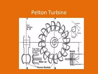
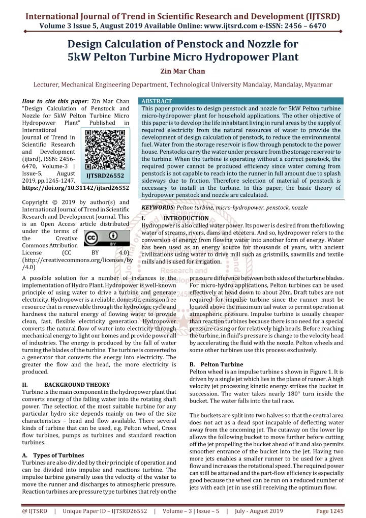
International Journal of Trend in Scientific Research and Development (IJTSRD) Volume 3 Issue 5, August 2019 Available Online: www.ijtsrd.com e-ISSN: 2456 – 6470 Design Calculation of Penstock and Nozzle for 5kW Pelton Turbine Micro Hydropower Plant Zin Mar Chan Lecturer, Mechanical Engineering Department, Technological University Mandalay, Mandalay, Myanmar How to cite this paper: Zin Mar Chan "Design Calculation of Penstock and Nozzle for 5kW Pelton Turbine Micro Hydropower Plant" International Journal of Trend in Scientific Research and Development (ijtsrd), ISSN: 2456- 6470, Volume-3 | Issue-5, August 2019, pp.1245-1247, https://doi.org/10.31142/ijtsrd26552 Copyright © 2019 by author(s) and International Journal of Trend in Scientific Research and Development Journal. This is an Open Access article distributed under the terms of the Creative Commons Attribution License (CC (http://creativecommons.org/licenses/by /4.0) A possible solution for a number of instances is the implementation of Hydro Plant. Hydropower is well-known principle of using water to drive a turbine and generate electricity. Hydropower is a reliable, domestic, emission free resource that is renewable through the hydrologic cycle and hardness the natural energy of flowing water to provide clean, fast, flexible electricity generation. Hydropower converts the natural flow of water into electricity through mechanical energy to light our homes and provide power all of industries. The energy is produced by the fall of water turning the blades of the turbine. The turbine is converted to a generator that converts the energy into electricity. The greater the flow and the head, the more electricity is produced. II. BACKGROUNDTHEORY Turbine is the main component in the hydropower plant that converts energy of the falling water into the rotating shaft power. The selection of the most suitable turbine for any particular hydro site depends mainly on two of the site characteristics – head and flow available. There several kinds of turbine that can be used, e.g. Pelton wheel, Cross flow turbines, pumps as turbines and standard reaction turbines. A.Types of Turbines Turbines are also divided by their principle of operation and can be divided into impulse and reactions turbine. The impulse turbine generally uses the velocity of the water to move the runner and discharges to atmospheric pressure. Reaction turbines are pressure type turbines that rely on the ABSTRACT This paper provides to design penstock and nozzle for 5kW Pelton turbine micro-hydropower plant for household applications. The other objective of this paper is to develop the life inhabitant living in rural areas by the supply of required electricity from the natural resources of water to provide the development of design calculation of penstock, to reduce the environmental fuel. Water from the storage reservoir is flow through penstock to the power house. Penstocks carry the water under pressure from the storage reservoir to the turbine. When the turbine is operating without a correct penstock, the required power cannot be produced efficiency since water coming from penstock is not capable to reach into the runner in full amount due to splash sideways due to friction. Therefore selection of material of penstock is necessary to install in the turbine. In this paper, the basic theory of hydropower penstock and nozzle are calculated. KEYWORDS: Pelton turbine, micro-hydropower, penstock, nozzle I. INTRODUCTION Hydropower is also called water power. Its power is desired from the following water of streams, rivers, dams and etcetera. And so, hydropower refers to the conversion of energy from flowing water into another form of energy. Water has been used as an energy source for thousands of years, with ancient civilizations using water to drive mill such as gristmills, sawmills and textile mills and is used for irrigation. Published in IJTSRD26552 BY 4.0) pressure difference between both sides of the turbine blades. For micro-hydro applications, Pelton turbines can be used effectively at head down to about 20m. Draft tubes are not required for impulse turbine since the runner must be located above the maximum tail water to permit operation at atmospheric pressure. Impulse turbine is usually cheaper than reaction turbines because there is no need for a special pressure casing or for relatively high heads. Before reaching the turbine, in fluid’s pressure is change to the velocity head by accelerating the fluid with the nozzle. Pelton wheels and some other turbines use this process exclusively. B.Pelton Turbine Pelton wheel is an impulse turbine s shown in Figure 1. It is driven by a single jet which lies in the plane of runner. A high velocity jet processing kinetic energy strikes the bucket in succession. The water takes nearly 180 turn inside the bucket. The water falls into the tail race. The buckets are split into two halves so that the central area does not act as a dead spot incapable of deflecting water away from the oncoming jet. The cutaway on the lower lip allows the following bucket to move further before cutting off the jet propelling the bucket ahead of it and also permits smoother entrance of the bucket into the jet. Having two more jets enables a smaller runner to be used for a given flow and increases the rotational speed. The required power can still be attained and the part-flow efficiency is especially good because the wheel can be run on a reduced number of jets with each jet in use still receiving the optimum flow. @ IJTSRD | Unique Paper ID – IJTSRD26552 | Volume – 3 | Issue – 5 | July - August 2019 Page 1245
International Journal of Trend in Scientific Research and Development (IJTSRD) @ www.ijtsrd.com eISSN: 2456-6470 Calculation of Penstock Diameter, 0.43 P 0.62 D Calculation of penstock velocity, Q = AVp Total length of penstock, lp = 5 + ) 45 sin( Calculation of penstock thickness, 800 D tp (2) 0.65 H (3) 45 (4) 5 Figure: 1. Typical Pelton Turbine III. A penstock is a pipe that conveys the flow the fore bay to the turbine. The penstock pipes start downstream of the fore bay. The potential energy of water at the fore bay is converted into kinetic energy at the turbine via the penstock pipe. Because the flow is conveyed under the pressure, it is important for the pipe design to be safe. The penstock is on steep ground slopes, such a pipe burst can cause landsides and other stability problems. Pipe line is connected to a reservoir at its upper end and has a control gate of the water and for regulating the discharge of the water. The penstock pipe usually constitutes a significant portion of the construction cost. In this research, choose the mild steel for penstock material, an economical diameter such that the head loss is within acceptable limits and wall thickness. So the pipe is safe for the design head and any surge effects that may result from sudden blockage of the penstock. The function of the nozzle of the pelton wheel is to convert the available pressure energy into the high velocity energy in the form of jet. The required quantity of water is proportional to the load on the turbine. Nozzle design is based on the standard dimensions and shape of prototypes. IV. DESIGN CONSIDERATION OF PENSTOCK AND NOZZLE The following formulae can be used to determine economical penstock diameter and nozzle for a hydroelectric project. Diameter of penstock plays an important role in a hydroelectric power plant. The flow rate depends on the size of penstock. If the head is high, the smaller flow rate must require. On the other hand, if the head is low, the larger flow rate must require. Specification data to design penstock and nozzle are shown in Table 1. Table1. Specification Data for Wind Turbine Blade Description Symbol Power(generator) net head flow rate jet diameter overall efficiency mechanical efficiency efflux coefficient generator efficiency velocity coefficient Calculation of Power output for Turbine, Power MATERIAL AND METHOD (5) 400 Calculation of Head Losses, 2 p v Head loss at entrance, he = (6) f 2g Where, Coefficient of entrance loss, f = 0.5 2 f l v p Friction head loss, (7) h f 2gD p f = 0.023 2 v p Head loss due to bent, (8) h k b 2g 2 v p Head loss at valves, (9) h f v 2g f = 0.1 2 v p Head loss at pipe reducer, (10) h f r 2g f = 0.25 Table2. Results Data of Penstock Power output of turbine Economical penstock diameter Velocity of water in penstock Total length of penstock Thickness of penstock Head loss at pipe inlet (entrance) Head loss due to pipe friction Head loss due to bends Head loss at valves Head loss at pipe reducer P Dp Vp Ip tp he hf hb hv hp 7.35 kW 0.123 m 1.195m/s 74 m 2.26 mm 0.0364 m 0.84 m 0.013 m 0.007 m 0.0182 m Value 5 45 0.0142 m3/s 25.07 80 85 0.84 80 0.98 Unit kW m Pg H Q d ηo ηm ηg Cv mm % % - % - Calculation of Nozzle Outlet Diameter, sinα Q d (11) 1 2.66 μ c H generator Power output of turbine (1) v η η g m @ IJTSRD | Unique Paper ID – IJTSRD26552 | Volume – 3 | Issue – 5 | July - August 2019 Page 1246
International Journal of Trend in Scientific Research and Development (IJTSRD) @ www.ijtsrd.com eISSN: 2456-6470 5 kW. The permissible velocity in the penstock is 1.195 m/s, penstock diameter is 0.123 m and 74 m pipe length are arranged. Pressure variations through the pipe are calculated. The designed nozzle is aimed to use in Pelton turbine. It is the main part of the Pelton turbine because the available fluid energy is converted into kinetic energy by a nozzle. In this paper, single jet nozzle is used because it is micro hydropower plant. So, single jet nozzle is selected for this site. The designed Pelton turbine can develop a power of 5 kW and the head is 45 m. The designed flow rate has 0.0142 m3/s. And then, the designed jet diameter of nozzle has 25.07 mm, 30.09 mm the outlet diameter of the nozzle respectively. The other important dimensions of the nozzle varied depend upon the outlet diameter of the nozzle. VI. ACKNOWLEDGEMENTS The author is deeply grateful to Dr. Kyaw Aung, Professor and Head of Mechanical Engineering Department, Technological University (Mandalay) for his willingness to share his ideas helpful suggestions on this paper writing. REFERENCES [1] Bikash Pandey, “Hydroelectric Energy: Renewable Energy and the Environment”, 4th edition, 2016 Figure: 2. Nozzle Dimensions Table3. Results Data of Nozzle Items C s x d I r R h e f Values 0.63 d1 1.35 d1 0.503 d1 0.63 d1 3.17 d1 0.705 d1 2.2 d1 0.6 d1 0.05 d1 1.13 d1 V. Hydroelectric power has been important in the provision of electricity. In hydropower plant, penstock is one of the most important parts to carry water for turning turbine. Penstocks are supplied the water from the fore bay tank to the turbine. In this paper, penstock and nozzle design are considered. A penstock is a pressure conduit which conveys water from a source to a hydraulic turbine. Penstock requirements are varied considerably to suit on physical and economic conditions. The net head must be 45 m to generate CONCLUSIONS [2] Wiley Students, “Fundamental of Fluid Mechanics”, 6th edition, 2004 [3] S. S. Rattan, “Strength of MaterialE. s”, 2nd edition, 2001 [4] Zh. Zhang, “Pelton Turbines”, 2nd edition, 2000 [5] E. Divatia, “Manual on Design Fabrication, Erection and Maintenance of Steel Penstocks @ IJTSRD | Unique Paper ID – IJTSRD26552 | Volume – 3 | Issue – 5 | July - August 2019 Page 1247