Download
1 / 6
60 likes | 63 Vues
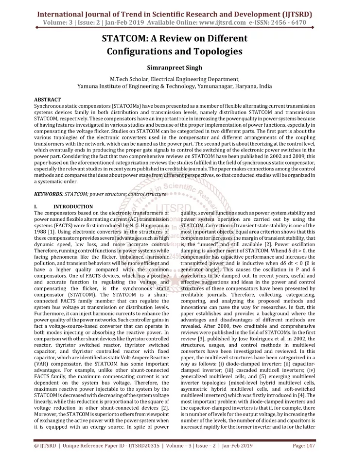
Synchronous static compensators STATCOMs have been presented as a member of flexible alternating current transmission systems devices family in both distribution and transmission levels, namely distribution STATCOM and transmission STATCOM, respectively. These compensators have an important role in increasing the power quality in power systems because of having features investigated in various studies and because of the proper implementation of power functions, especially in compensating the voltage flicker. Studies on STATCOM can be categorized in two different parts. The first part is about the various topologies of the electronic converters used in the compensator and different arrangements of the coupling transformers with the network, which can be named as the power part. The second part is about theorizing at the control level, which eventually ends in producing the proper gate signals to control the switching of the electronic power switches in the power part. Considering the fact that two comprehensive reviews on STATCOM have been published in 2002 and 2009, this paper based on the aforementioned categorization reviews the studies fulfilled in the field of synchronous static compensator, especially the relevant studies in recent years published in creditable journals. The paper makes connections among the control methods and compares the ideas about power stage from different perspectives, so that conducted studies will be organized in a systematic order. Simranpreet Singh "STATCOM: A Review on Different Configurations and Topologies" Published in International Journal of Trend in Scientific Research and Development (ijtsrd), ISSN: 2456-6470, Volume-3 | Issue-2 , February 2019, URL: https://www.ijtsrd.com/papers/ijtsrd20315.pdf Paper URL: https://www.ijtsrd.com/engineering/electrical-engineering/20315/statcom-a-review-on-different-configurations-and-topologies/simranpreet-singh<br>

E N D
International Journal of Trend in Scientific Research and Development (IJTSRD) Volume: 3 | Issue: 2 | Jan-Feb 2019 Available Online: www.ijtsrd.com e-ISSN: 2456 - 6470 STATCOM: A Review on Different Configurations and Topologies Simranpreet Singh M.Tech Scholar, Electrical Engineering Department, Yamuna Institute of Engineering & Technology, Yamunanagar, Haryana, India ABSTRACT Synchronous static compensators (STATCOMs) have been presented as a member of flexible alternating current transmission systems devices family in both distribution and transmission levels, namely distribution STATCOM and transmission STATCOM, respectively. These compensators have an important role in increasing the power quality in power systems because of having features investigated in various studies and because of the proper implementation of power functions, especially in compensating the voltage flicker. Studies on STATCOM can be categorized in two different parts. The first part is about the various topologies of the electronic converters used in the compensator and different arrangements of the coupling transformers with the network, which can be named as the power part. The second part is about theorizing at the control level, which eventually ends in producing the proper gate signals to control the switching of the electronic power switches in the power part. Considering the fact that two comprehensive reviews on STATCOM have been published in 2002 and 2009, this paper based on the aforementioned categorization reviews the studies fulfilled in the field of synchronous static compensator, especially the relevant studies in recent years published in creditable journals. The paper makes connections among the control methods and compares the ideas about power stage from different perspectives, so that conducted studies will be organized in a systematic order. KEYWORDS: STATCOM; power structure; control structure I. INTRODUCTION The compensators based on the electronic transformers of power named flexible alternating current (AC) transmission systems (FACTS) were first introduced by N. G. Hingorani in 1988 [1]. Using electronic converters in the structures of these compensators provides several advantages such as high dynamic speed, low loss, and more accurate control. Therefore, running control functions in power systems while facing phenomena like the flicker, imbalance, harmonic pollution, and transient behaviors will be more efficient and have a higher quality compared with the common compensators. One of FACTS devices, which has a positive and accurate function in regulating the voltage and compensating the flicker, is the synchronous static compensator (STATCOM). The STATCOM is a shunt- connected FACTS family member that can regulate the system bus voltage at transmission or distribution levels. Furthermore, it can inject harmonic currents to enhance the power quality of the power networks. Such controller gains in fact a voltage-source-based converter that can operate in both modes injecting or absorbing the reactive power. In comparison with other shunt devices like thyristor controlled reactor, thyristor switched reactor, thyristor switched capacitor, and thyristor controlled reactor with fixed capacitor, which are identified as static Volt-Ampere Reactive (VAR) compensator, the STATCOM has some important advantages. For example, unlike other shunt-connected FACTS family, the maximum compensating current is not dependent on the system bus voltage. Therefore, the maximum reactive power injectable to the system by the STATCOM is decreased with decreasing of the system voltage linearly, while this reduction is proportional to the square of voltage reduction in other shunt-connected devices [2]. Moreover, the STATCOM is superior to others from viewpoint of exchanging the active power with the power system when it is equipped with an energy source. In spite of power quality, several functions such as power system stability and power system operation are carried out by using the STATCOM. Correction of transient state stability is one of the most important objects. Equal area criterion shows that this compensator increases the margin of transient stability, that is, the “unused” and still available [2]. Power oscillation damping is another merit of STATCOM. Whend δ dt > 0, the compensator has capacitive performance and increases the transmitted power and is inductive when dδ dt < 0 (δ is generator angle). This causes the oscillation in P and δ waveforms to be damped out. In recent years, useful and effective suggestions and ideas in the power and control structures of these compensators have been presented by creditable journals. Therefore, collecting, categorizing, comparing, and analyzing the proposed methods and innovations can pave the way for researches. In fact, this paper establishes and provides a background where the advantages and disadvantages of different methods are revealed. After 2000, two creditable and comprehensive reviews were published in the field of STATCOMs. In the first review [3], published by Jose Rodriguez et al. in 2002, the structures, usages, and control methods in multilevel converters have been investigated and reviewed. In this paper, the multilevel structures have been categorized in a way as follows: (i) diode-clamped inverter; (ii) capacitor- clamped inverter; (iii) cascaded multicell inverters; (iv) generalized multilevel cells; and (5) emerging multilevel inverter topologies (mixed-level hybrid multilevel cells, asymmetric hybrid multilevel cells, and soft-switched multilevel inverters) which was firstly introduced in [4]. The most important problem with diode-clamped inverters and the capacitor-clamped inverters is that if, for example, there is n number of levels for the output voltage, by increasing the number of the levels, the number of diodes and capacitors is increased rapidly for the former inverter and to for the latter @ IJTSRD | Unique Reference Paper ID - IJTSRD20315 | Volume – 3 | Issue – 2 | Jan-Feb 2019 Page: 147
International Journal of Trend in Scientific Research and Development (IJTSRD) @ www.ijtsrd.com eISSN: 2456-6470 inverter. The increase in diode and capacitor count imposes limitations due to the complexity of the control algorithm and the bulkiness of the circuit. In spite of these drawbacks, one advantage is that they have common direct current (DC)-link voltage and do not suffer from voltage balancing of levels. In addition, voltage levels have been increased without requiring accurate voltage matching. However, this can be a serious problem in high-voltage applications because using the common voltage source in this level not only is not practicable but also can reduce the reliability because all capacitors are dependent on one DC link. In the structures of cascaded multicell inverters, some two-leg converters are put together in series in each phase, and the voltage of each phase is obtained through adding up the voltages of the converters of the same phase. This structure is much simpler than diode and capacitor-clamped inverter schemes. In generalized multilevel cells, the two-level, three-level, and four-level to n- level ones are put next to each other. In this design, every level of voltage is balanced by itself and independent from the characteristics of the load. In other words, this topology provides a multilevel structure that can balance any level of DC voltage by means of specialized controls. In mixed-level hybrid multilevel cells, the multilevel structures of diode- clamped inverter and capacitor-clamped inverter are replaced with the full-bridge cells in the cascaded multicell inverter schemes, and therefore, the number of DC sources is decreased. This method can be useful in high power and high- voltage applications. However, using diode-clamped and capacitor-clamped inverters increases the complexity of the control algorithms. In asymmetric hybrid multilevel cells, the levels of the DC voltage in cells are not equal, and the converters of every cluster suffer from different stress. Although this can increase the cost, it causes more levels to be produced with the same number of devices when compared with symmetric multilevel inverters. Also, controlling the balance of the capacitor voltage in such scheme may be more difficult compared with the topologies where the voltages of all capacitors must be set in a fixed value. Therefore, the modulation circuit becomes more complex. Referring to the studies conducted in [5–10], the paper [3] has investigated the methods based on using soft switching and the combinations of the methods zero-voltage transition and auxiliary resonant commutated pole. Also in [3], the modulation methods have been divided into two groups of switching in high frequency and switching in the main frequency. The methods sinusoidal pulse–width modulation (PWM) and space vector PWM fall into the first group, and the methods selective harmonic eliminations and space vector control fall into the second one. Finally, the practical usages of the multilevel converters in multilevel rectifiers and running the motors and power systems were discussed. The second review on STATCOM was published by B. Singh et al. in 2009 [11]. In this paper, they approached STATCOM with two perspectives of multilevel converters and multipulse converters. Referring to Reference [12], they have stated that the multilevel structures have preference over the multipulse ones, which is based on magnetic coupling. There are important reasons for this preference, for example, the implementation of a multipulse structure is costly and the multilevel converters, especially the cascade type, are more reliable. However, because each project has its own specific features, the role of the multipulse converters cannot be easily ignored. The control strategies of STATCOM have been surveyed in [12], and the basis of the control architecture in STATCOM has been reported as Figure 1 shows. Figure 1. The basis of the control architecture in synchronous static compensator (STATCOM) [12]. VSC, voltage-source converter; AC, alternating current; DC, direct current; GTO, gate turn-off thyristor. Also in this convertor, bipolar voltage blocking capability is achieved by the use of an asymmetric integrated gate commutated thyristor and a fast recovery diode instead of a single symmetrical device, which maximizes the convertor power rating and makes natural air cooling realizable. In the control part, the control methods, techniques, and the comparison of their advantages and disadvantages are studied. II. CONVERTER SECTION TOPOLOGY The structures of diode-clamped inverter, capacitor-clamped inverter, and cascade multilevel converter (CMC) have been used many times in papers, and their advantages and disadvantages are well known. Anyway, the CMC structures have received more attention in industry and research areas because of their more simplicity and reliability and easier control, so that in [20,21], the CMC converter was used in STATCOM structure to regulate the bus voltage, and the paper [22] has also reported an implementation of sample of transmission STATCOM with 5-HB arrangement and 12 Mvar. The proposed structure given by [22] has been analyzed by [23]. The design for using two parallel sets of the CMC is proposed in [24] under the name of extended CMC. In fact, this structure, whose main profile is shown in Figure 2, has looked at improving the reliability from device redundancy viewpoint, whereas [25] has introduced H-bridge building blocks redundancy instead of the device redundancy and shown that the proposed idea can reduce the total harmonic distortion of the current, equal losses despite the two converter structures and a more capacity in reactive compensation for the extended modular multilevel converters in comparison with the modular multilevel converters. In [26], a kind of hybrid structure named hybrid cascade has been introduced according to Figure 3. In this structure, one converter of each phase operates in the base frequency with a high voltage, and the other works in a high frequency with a low voltage. This causes the number of the output voltage levels to be more than the common number 2N+ 1(N is the number of the converters). According to the figure, it can be seen that the phases have a triangular arrangement and the component of zero sequence current (i0) runs into the delta connection, which has an important role in controlling the DC voltage and balancing the load. @ IJTSRD | Unique Reference Paper ID - IJTSRD20315 | Volume – 3 | Issue – 2 | Jan-Feb 2019 Page: 148
International Journal of Trend in Scientific Research and Development (IJTSRD) @ www.ijtsrd.com eISSN: 2456-6470 DC-link capacitor have been considered unequally. By considering Figure 7, such structure is called asymmetric CMC structures. As it can be seen, the capacitors voltages are 1.2, 2, and 6 Vdc in each phase. In these structures, the converters with higher DC voltage have less switching frequency and more power transmission and vice versa. These structures, also known as multivoltage, cause a harmonic decrease in the voltage and therefore, a decrease in the AC filter complexity. Only the converters with a low voltage have a high switching frequency, so the system’s total loss will diminish. Also, only the converters with a high voltage need insulated gate bipolar transistor with a high blocking voltage; therefore, the system’s total loss will decrease even more. III. SYNCHRONOUS STATIC STRUCTURES IN CONTROL PART Control strategies in static synchronous compensators are mostly carried out by digital computers. Therefore, analog to digital convertors became more practical. So, most of the controllers and signals are digital base. However, all systems specially power systems are continuous, and for using the advantages of digital computers, measured signals samples are digitized by sample and hold module. Finally, these signals are applied to digital computers as a processor. Moreover, a digital-analog hybrid control methods were recently introduced, which have some merits such as to improve the performance of traditional analog adaptive control. In this section, the control structures that are employed for a STATCOM are discussed. Obviously, the topologies presented in the power section require their own control techniques. Therefore, it can be said that ideas in the power part bring ideas in control structures. It is noticeable that the proposed control structures for the new topologies of the converter in STATCOM may be generalizable to simple converters and even vice versa. For example, it may be possible to use a control method presented for a simple synchronous static converter in the control systems of the power parts of the new structures. Therefore, it is important to consider a proposed control method from different perspectives. In a categorization, the control methods can be divided as follows: 1.STATCOM control methods by the simple two-level and six-pulse converter; 2.STATCOM control methods by different structures of the converter; and 3.STATCOM control methods by different topologies of the coupling transformer. Synchronous static compensator control methods by the simple two-level and six-pulse converte. Synchronous static compensator control methods by the simple two-level and six-pulse converter. One of the simplest methods for STATCOM control aiming at voltage regulation has been introduced in [27]. In this control loop, depicted in Figure 17, the capacitor voltage, which decreases because of energy exchange with the compensator for the switching and resistive losses of the compensator. One of the control methods that has a close relationship with determining algorithms for reactive components of the reference current has been studied in [29,30]. Mr. Akagi first presented the algorithm and the theory of instantaneous reactive power, and then many papers such as have been published on this subject. The general block diagram of this control design has been presented in Figure 19. As it can be seen, the reference currents are obtained through one of the mentioned COMPENSATOR Figure2. Combinational structure named hybrid cascade [26]. MC, multilevel converter Mr. Hirofomi Akagi has categorized the STATCOM based on the modular arrangement of the H-bridges or choppers into four classes [27]: (1) single star bridge cells (SSBCs); (2) single delta bridge cells (SDBCs); (3) double star copper cells (DSCCs); and (4) double star bridge cells (DSBCs). The CMC- SDBC structure has been presented in [28,29] and is depicted in Figure 4. It is seen that firstly, the connection of the phases and the delta arrangement allows the negative sequence of the reactive power to circulate and secondly, this structure has the capability of connecting to a 6.6-kV network without coupling transformer. Also, as the name of this CMC type implies, each phase contains series converters. The DSCC type shown in Figure 5 is reported in [30]. These converters contain choppers in each phase arranged in two parts and are connected to each other and the network through a center tap inductor. Such structures have functions in the modes of rectifier, inverter, inductive, and capacitive. Two other types of CMC named SSBC and DSBC have been also introduced in [27,29], which are illustrated in Figure 6. There are also comparisons among four types of CMCs from different perspectives with a summary in Table I. In arrangements where there is the ability of the rotational circulation such as SDBC and DSCC, it is possible to control the negative sequence of the reactive power. Therefore, the structures are appropriate for compensating the flicker. Another important implication of the comparisons is the usages of the four structures. Accordingly, the arrangements DSCC and DSBC are used both in the motor drive system as flicker compensation, high-voltage DC systems, and wind/solar power conditioning, while the other two structures are used only in network usages, especially voltage regulation and flicker compensation. The implementation of a seven-level SSBC in a 10-kVA and 200-V laboratory area has been reported in [31]. Because circulating current cannot be passed among phases, in this topology, negative sequence reactive power cannot be controlled. So, this structure cannot be considered as effective compensator in some functions such as voltage flicker mitigation. Experimental results in [29] show that SDBC can mitigate voltage flicker effectively because this structure can pass the circulating current in delta connection and compensate the negative sequence reactive power. It has to be mentioned that the multilevel structures have been studied symmetrically mostly. It means that the DC voltage in converters has been equalized by balancing algorithms. But in some studies such as [20,32–36], the voltages of the @ IJTSRD | Unique Reference Paper ID - IJTSRD20315 | Volume – 3 | Issue – 2 | Jan-Feb 2019 Page: 149
International Journal of Trend in Scientific Research and Development (IJTSRD) @ www.ijtsrd.com eISSN: 2456-6470 algorithms, and after being compared with the compensating current and passing through a PI controller, they are sent to produce the gate command. Reference [35] deals with the STATCOM through the compensating perspective that produces admittance and conductance. In this control scheme, the admittance controls the component of the current’s positive sequence, and the conductance controls the component of the negative sequence current. It should be mentioned that the component of negative sequence is the controlling factor for compensating imbalance and the component of positive sequence is the controlling factor for voltage oscillation. The STATCOM control has been presented based on feedback linearization and without any simplifying premises, by using nonlinear control in [36], and has been implemented on IEEE-118 bus system along with the complete model of the generator and the network. IV. CONTROL OF STATCOM Synchronous static compensator control by different converter structures The control systems in compensators based on CMC must focus on both balancing the capacitor voltage in the DC link and following the main functions of the compensator. Based on these two functions, the discussion can be categorized. 3.2.1. Control methods with the compensator’s main goals (specially voltage regulation and flicker compensation). The utilization of STATCOM based on CMC aiming at decreasing the flicker and by using field database has been reported in [21]. The control system utilized includes two parts: internal control and external control, which are depicted in Figure 20. As it can be seen, in the internal control, the control loops of Id and Iq are controlled separately and independently (decoupled). Id control loops stabilize the DC-link voltage, and Iq control loop is responsible for decreasing the flicker. In the external control, the voltage at the PCC is compared with the desirable value, and after passing through a PI controller, it is inserted to the internal control loop as Iqref. In [18], a control system is introduced, which has been installed in a Japan’s power station. The compensator is 20 MVA, which consists of two parallel sets of 10 MVA, and every set includes six VSCs of 1.67 MVA with a DC link of 1600 V and insulated gate bipolar transistors of 1200 A and 3300 V. The control structure is given in Figure 3. In this control loop, the load current is one of the most important input signals. The load current in fact consists of the furnace current and the furnace parallel capacitors and has potential to resonance with the STATCOM current that can be harmful. In order to cope with this problem, first, the variations of the basic frequency are extracted, and then the frequencies leading to resonance are filtered. A nonlinear control structure has been reported by [29] aiming at decreasing the flicker, compensating the imbalance, and compensating the reactive power, which has been used in the CMC-11H-bridge building blocks-based compensator. The most important advantage of this method is that it needs to set only one parameter, while in PI compensators, used for controlling the AC and DC voltages, it is necessary to set both the proportion and the integral coefficients properly. The STATCOM based on multilevel modular multilevel categorized in four types of SSBC, SDBC, DSCC, and DSBC by Akagi, was investigated separately in the power section. The control structure-type SDBC has been reported in [27,29]. This structure makes it possible to control the components of the negative sequence of the reactive power by circulating current inside the delta. Figure3. Synchronous static compensator based on cascade multilevel converter aiming at flicker decrease. PCC, point of common coupling V. The recent studies and researches on STATCOM have revealed that different compensator structures have come from the suggestions and ideas in the two parts of control and power. In this paper, various structures suggested in the two sections have been investigated in two separate parts, and the advantages and disadvantages of each topology compared with other structures were discussed. The advances in the converter part in STATCOM are the results of successful achievements in electronic areas. Also, a science such as materials science has got to have great impacts formerly on electronics and then on power electronics, and it is expected that also in the future, such changes revolutionize the world of power industry and shed light to new directions and horizons for the researchers. The other point that can be inferred from the creditable papers of recent years is that laboratory implementation and even industrial installation and implementation have received more attention compared with the past and desirable results that have been reported. It means that the identification of STATCOM’s physical identity and its function in the face of undesirable phenomena and any kind of shortage in power systems has been put in the right direction, so that the theoretical and practical results have good consistency. Therefore, it can be expected that by using the studies and researches of the control engineering and electronics engineering sciences in STATCOM aiming at advancing the power part of this compensator, it will be seen more reports of implementing the industrial projects in the coming years. REFERENCES [1]Padiyar KR. FACTS Controllers in Power Transmission and Distribution. Anshan: Tunbridge Wells; 2009. Conclusions [2]Hingorani NG, Gyugyi L. Understanding FACTS: Concepts and Technology of Flexible AC Transmission Systems. Institute of Electrical and Electronics Engineers: New York; 1999. [3]Rodriguez J, Lai J-S, Peng FZ. Multilevel inverters: a survey of topologies, controls, and applications. IEEE Transactions on Industrial Electronics 2002; 49(4):724– 738. [4]Song BM, Gurol S, Jeong CY, Yoo DW, Lai JS. A soft- switching high-voltage active power filter with flying capacitors for urban maglev system applications, in Conf. Rec. IEEE-IAS Annu. Meeting, Chicago, IL, 2001; 1461–1469. cascade converters, [5]Song BM, Lai JS. A multilevel soft-switching inverter with inductor coupling. IEEE Transactions on Industry Applications 2001; 37:628–636. [6]Yuan X, Orgimeister G. ARCPI resonant snubber for the neutral point-clamped (NPC) inverter. IEEE @ IJTSRD | Unique Reference Paper ID - IJTSRD20315 | Volume – 3 | Issue – 2 | Jan-Feb 2019 Page: 150
International Journal of Trend in Scientific Research and Development (IJTSRD) @ www.ijtsrd.com eISSN: 2456-6470 Transactions on Industry Applications 2000; 36:586– 595. distributed generation power systems incorporating renewable energy resources,” Int. J. Energy Res., no. October, pp. 1–40, Nov. 2018. [7]Yuan X, Barbi I. Zero voltage switching for three level capacitor clamping inverter. IEEE Transactions on Power Electronics 1999; 14:771–781. [22]Venturi M, Mohrdieck C, Friedrich J. Mercedes-Benz b- class fuel cell: the world largest hydrogen vehicle fuel cell fleet experience. In: Proceedings of Electric Vehicle Symposium and Exhibition (EVS27), 2013 World. IEEE; 2013 [8]Yuan X. A transformer assisted zero-voltage switching scheme for the neutral-point-clamped (NPC) inverter, in Proc. IEEE APEC’99, 1999; 1259–1265. [23]Ahn Byung Ki, Tae Won Lim. Fuel cell vehicle development at Hyundai-Kia Motors. In: Proceedings of the 1st international forum on strategic technology, IEEE; 2006 [9]Dijkhuizen FR, Duarte JL, van Gorningen WDH. Multilevel converter commutated pole, in Conf. RecIEEE-IAS Annu. Meeting, 1998; 1440–1446. with auxiliary resonant [24]Bindeshwar Singh, k.s. Verma, Deependra Singh, C.N. Singh, Archnasingh, Ekta Agrawal, Rahul Dixit, Baljiv Tyagi “Introduction To Facts Controllers A Critical Review”. International Journal of Reviews in Computing 31st December 2011. Vol. 8 pp 17-38. [10]Teichmann R, O’Brian K, Bernet S. Comparison of multilevel ARCP topologies, in Proc. Int. Power Electronics Conf., Tokyo, Japan, 2000; 2035–2040. [11]Singh B, Saha R, Chandra A, Al-Haddad K. Static synchronous compensators (STATCOM): a review. IET Power Electronics 2009; 2(4):297–324. [25]Bhim Singh and R. Saha, “Modeling of 18-Pulse STATCOM for Power System Applications” Journal of Power Electronics, Vol. 7, No. 22, April 2007 [12]Lai J-S, Peng FZ. Multilevel converters – a new breed of power converters. IEEE Transactions on Industry Applications 1996; 32(3):509–517. [26]Zhiping Yang, Mariesa L. Crow, Chen Shen, Lingli Zhang,”The Steady State Characteristics of A STATCOM with Energy Storage” IEEE Transc. 2000. [13]Tahri A, Draou A, Benghanem M. A fast current control strategy of a PWM inverter used for static VAR compensation. Proc. IEEE 24th Annual Conf. Industrial Electronics Society, IECON’98, 31 August– 4 September 1998, vol. 1, pp. 450–455 [27]O. Krishan and Sathans, “Design and Techno-Economic Analysis of a HRES in a Rural Village,” Procedia Comput. Sci., 6th International Conference on Smart Computing and Communications, ICSCC 2017, 7-8 December 2017, Kurukshetra, India vol. 125, pp. 321–328, 2018. [14]Wuest D, Jenni F. Space vector based current control schemes for voltage source inverters. IEEE Power Electronics Specialists Conf., PESC’93, 20–24 June 1993; 986–992. [28]O. Krishan and Sathans, “Frequency regulation in a standalone wind-diesel hybrid power system using pitch-angle controller,” in Proceedings of the 10th INDIACom; 2016 3rd International Conference on Computing for Sustainable Global Development, INDIACom 2016, 2016. [15]Jiang Y, Ekstrom A. Applying PWM to control overcurrents at unbalanced faults of forced-commutated VSCs used as static VAR compensators. IEEE Transactions on Power Delivery 1997; 12(1):273–278. [29]Kundur P.: ‘Power system stability and control’(McGraw- Hill, 1994) [16]Tang Y, Xu L. A new converter topology for advanced static VAR compensation in high power applications. IEEE Industry Applications Society Annual Meeting, Conf. Record, 2–8 October 1993, vol. 2, pp. 947–953 [30]B. Singh, R.Saha, A. Chandra, K. Al-Haddad,”Static Synchronous Compensators (STATCOM): A Review”, Published in IET Electronics on 28th January 2008. [17]Wuest D. An improved PWM optimization method for a static reactive power compensator with self- commutated inverter. PESC Power Electr. Specialists Conf., Cambridge, MA, 1991; 521–529. [31]Sam Koohi-Kamali, V.V.Tyagi , N.A. Rahim, N.L.Panwar, H.Mokhlis. “Emergence of energy storage technologies as the solution for reliable operation of smart power systems: A review”. Renewable and Sustainable Energy Reviews 25 (2013) 135–165 Elsevier Ltd. [18]Malesani L, Tomasin P. PWM current control techniques of voltage source converters – a survey, Int. Conf. Proc. Industrial Electronics, Control and Instrumentation, IECON’93, 15–19 November 1993, vol. 2, pp. 670–675. [32]H.F. Wang,”Modelling STATCOM into Power System ” Appl Energy 2013;105: 138–54. [33]Sano K, Takasaki M. A transformerless D-STATCOM based on a multi-voltage cascade converter requiring no DC sources, IEEE Energy Conversion Congress and Exposition (ECCE), Phoenix, AZ, pp. 3151 – 3158, 17–22 Sept. 2011. [19]Wang HF, Li F. Multivariable sampled regulators for the co-ordinated control of STATCOM AC and DC voltage. Proceedings of IEEE Generation, Transmission and Distribution 2000; 147(2):93–98. [20]O. Krishan and Sathans, “Optimum sizing and economical assessment of grid integrated hybrid system for a rural village: A case study,” in 1st IEEE International Conference on Power Electronics, Intelligent Control and Energy Systems, ICPEICES 2016, 2017. [34]Han C, Yang Z, Chen B, et al. Evaluation of cascade- multilevel converter-based STATCOM for arc furnace flicker mitigation. IEEE Transactions on Industry Applications 2007; 43(2):378–385. [35]Gultekin B, Ermis M. Cascaded multilevel converter- based transmission STATCOM: methodology and development of a 12 kV ±12 Mvar system design [21]O. Krishan and S. Suhag, “An updated review of energy storage systems: Classification and applications in @ IJTSRD | Unique Reference Paper ID - IJTSRD20315 | Volume – 3 | Issue – 2 | Jan-Feb 2019 Page: 151
International Journal of Trend in Scientific Research and Development (IJTSRD) @ www.ijtsrd.com eISSN: 2456-6470 power stage. IEEE Transactions on Power Electronics 2013; 28(11):4930–4950. Hbridge converter. IEEE Transactions on Power Electronics 2013; 28(1):101–111. [36]Gultekin B, Gercek CO, Atalik T, Deniz M. Design and implementation of a 154-kV ± 50-Mvar transmission STATCOM based on 21-level cascaded multilevel converter. IEEE Transactions on Industry Applications 2012; 48(3):1030–1045. [40]Akagi H. Classification, terminology, and application of the modular multilevel cascade converter (MMCC). IEEE Transactions on Power Electronics 2011; 26(11):3119– 3130. [41]Hagiwara M, Maeda R, Akagi H. Negative-sequence reactive-power control by a PWM STATCOM based on a modular multilevel cascade converter (MMCC-SDBC). IEEE Transactions on Industry Applications 2012; 48(2):3728–3735. [37]Mohammadi HP, Bina MT. A transformerless medium- voltage STATCOM topology based on extended modular multilevel converters. IEEE Transactions on Power Electronics 2011; 26(5):1534–1545. [38]Song W, Huang AQ. Fault-tolerant design and control strategy for cascaded H-bridge multilevel converter- based STATCOM. IEEE Transactions on Industrial Electronics 2010; 57(8):2700–2708. [42]Hagiwara M, Maeda R, Akagi H. Application of a modular multilevel cascade converter (MMCC-SDBC) to a STATCOM. Control of active power and negative- sequence reactive power. Electrical Engineering in Japan 2013; 183(4):33–44. [39]Sixing D, Liu J, Lin J, He Y. A novel DC voltage control method for STATCOM based on hybrid multilevel @ IJTSRD | Unique Reference Paper ID - IJTSRD20315 | Volume – 3 | Issue – 2 | Jan-Feb 2019 Page: 152