Download
1 / 3
30 likes | 70 Vues
The metal cutting process for material removing in turning process using a single point tool on the work piece will influence, the machining parameters in terms of efficiency under variable cutting conditions such as speed of the spindle , feed rate and depth of the cute rate during the removal of material in the form of chips from the cylindrical work piece. The HSS Single point cutting tool is one of the important tool for machining operations in many manufacturing industries. In this paper, the experimental analysis is performed and the effect of parameters like variable speed on the spindle, depth of the cut and feed on surface roughness, tool life and MRR are determined and compared. The work piece choosen for the experiment is S50C medium carbon steel with HSS single point Cutting tool and the results are obtained, calculated and tabulated. P. H. J. Venkatesh | R. Rudrabhi Ramu | M. S. R. Viswanath "Experimental Analysis of Machining Parameters on Turning with Single Point Cutting Tool" Published in International Journal of Trend in Scientific Research and Development (ijtsrd), ISSN: 2456-6470, Volume-4 | Issue-4 , June 2020, URL: https://www.ijtsrd.com/papers/ijtsrd30932.pdf Paper Url :https://www.ijtsrd.com/engineering/mechanical-engineering/30932/experimental-analysis-of-machining-parameters-on-turning-with-single-point-cutting-tool/p-h-j-venkatesh<br>

E N D
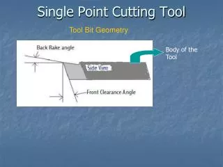
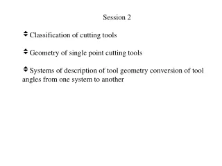
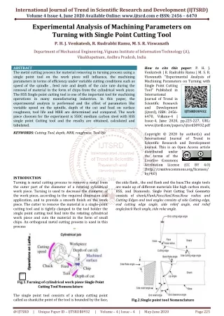
International Journal of Trend in Scientific Research and Development (IJTSRD) Volume 4 Issue 4, June 2020 2020 Available Online: www.ijtsrd.com e-ISSN: 2456 International Journal of Trend in Scientific Research and Development (IJTSRD) International Journal of Trend in Scientific Research and Development (IJTSRD) ISSN: 2456 – 6470 Experimental Analysis of Machining Parameters with Single Point Cutting Tool Venkatesh, R. Rudrabhi Ramu, M. S. R. Viswanath Experimental Analysis Turning w P. H. J. Venkatesh, f Machining Parameters on ith Single Point Cutting Tool Viswanath Department of Mechanical Engineering, Department of Mechanical Engineering, Vignans Institute of Information Technology (A) Visakhapatnam, Andhra Pradesh, India Vignans Institute of Information Technology (A), Visakhapatnam, Andhra Pradesh, India ABSTRACT The metal cutting process for material removing in turning process using a single point tool on the work piece will influence, the machining parameters in terms of efficiency under variable cutting conditions such as speed of the spindle , feed rate and de removal of material in the form of chips from the cylindrical work piece. The HSS Single point cutting tool is one of the important tool for machining operations in many manufacturing industries. experimental analysis is performed and the effect of parameters like variable speed on the spindle, depth of the cut and feed on surface roughness, tool life and MRR are determined and compared. piece choosen for the experiment is S50C medium carbon steel single point Cutting tool and the results are obtained, calculated and tabulated. KEYWORDS: Cutting Tool, depth, MRR, roughness, How to cite this paper: P. H. J. Venkatesh | R. Rudrabhi Ramu | M. S. R. Viswanath "Experimental Analysis of Machining Parameters on Turning with Single Point Cutting Tool" Published in International Journal of Trend in Scientific Research and Development jtsrd), ISSN: 2456- 6470, Volume-4 | 4, June 2020, pp.225-227, URL: www.ijtsrd.com/papers/ijtsrd30932.pdf How to cite this paper Venkatesh | R. Rudrabhi Ramu | M. S. R. Viswanath "Experimental Analysis of Machining Parameters on Turning with Single Point Cutting Tool" Published in International Journal of Trend in Scientific Research and Development (ijtsrd), ISSN: 2456 6470, Volume Issue-4, June 2020, pp.225 www.ijtsrd.com/papers/ijtsrd30932.pdf Copyright © 20 International Journal of Trend in Scientific Research and Development Journal. This is an Open Access article distributed under the terms of the Creative Commons Attribution License (http://creativecommons.org/licenses/ by/4.0) The metal cutting process for material removing in turning process using a single point tool on the work piece will influence, the machining in terms of efficiency under variable cutting conditions such as and depth of the cute rate during the removal of material in the form of chips from the cylindrical work piece. is one of the important tool for machining operations in many manufacturing industries. In this paper, the tal analysis is performed and the effect of parameters like depth of the cut and feed on surface roughness, tool life and MRR are determined and compared. The work piece choosen for the experiment is S50C medium carbon steel with HSS single point Cutting tool and the results are obtained, calculated and IJTSRD30932 roughness, Tool life Copyright © 2020 by author(s) and International Journal of Trend in Scientific Research and Development Journal. This is an Open Access article ibuted under the terms of the Creative Commons Attribution License (http://creativecommons.org/licenses/ (CC (CC BY BY 4.0) 4.0) INTRODUCTION Turning is metal cutting process to remove a the outer part of the diameter of a rotating cylindrical work piece. Turning is used to decrease the work piece, according to the required application, and to provide a smooth finish on the work piece. The cutter to remove the material cutting tool and is tightly clamped to the single point cutting tool feed into the rotating work piece and cuts the material in the form of small chips. An orthogonal metal cutting process process the side flank , the end flank and the base. are made up of different materials like HSS, and Diamonds. Single Point consists of shank,Flank,Face Cutting Edges and tool angles consists of s end cutting edge angle, s angle,back Rack angle, side rake angle. ove a metal from the end flank and the base.The single tools up of different materials like high carbon steels, Single Point Cutting Tool Geometry Face,Heel,Nose,Nose radius and and tool angles consists of side Cutting edge, side relief angle, end relief , side rake angle. diameter of a rotating cylindrical the diameter of required dimension and a smooth finish on the work is a single-point to the tool holder the cutting tool feed into the rotating cylindrical in the form of small chips. An orthogonal metal cutting process is used in this The image part with relationship ID rId14 was not found in the file. Fig.1.Turning of cylindrical work piece Cutting Tool Nomenclature Fig.1.Turning of cylindrical work piece Single Point Nomenclature The single point tool consists of a shar called as shank,the point of the tool is bounded by the face he point of the tool is bounded by the face, tool consists of a sharp cutting point Fig.2.Single point tool Fig.2.Single point tool Nomenclature @ IJTSRD | Unique Paper ID – IJTSRD30932 30932 | Volume – 4 | Issue – 4 | May-June 2020 2020 Page 225
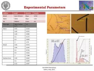
International Journal of Trend in Scientific Research and Development (IJTSRD) @ www.ijtsrd.com eISSN: 2456-6470 PARAMETERS EVALUATED USING TURNING PROCESS The experiment is conducted by considering HSS[2] single point tool operating on S50Cmedium carbon steel work piece in turning process.These machining test is performed on a conventional lathe machine. The work piece of cylindrical shape having a diameter of 30mm and a length of 350mm. A Lathe machine with a spindle speed range from 200rpm to 700 rpm was used for the machining.The machining center was driven with 6.5 kw electric motor. The experiment is performed under the dry machining environment.The tool life can be determined by mathematical relation for calculation of total length of effective cut.The tool life data is collected for each of the different cutting conditions and tabulated. S50C medium carbon steel composition: Table.1.S50C composition Grade C Mn S50C 0.47-0.53 0.60-0.90 0.030 0.15-0.35 0.035 S50C grade carbon steel is widely used in machine manufacturing, mechanical parts such as springs, gears, tension bars, the rollers, the axis, and the load spindle. Table 2.Process parameters of turning process Ra MRR N f d VC Diameter of the work piece D = 0.03m Length of the work piece, L= 0.35m For 250 rpm, Cutting speed in m/min VC= 1000 250 03 . 0 × × π Theoretical Surface Roughness in (μm) Material Remove Rate in cm3/min Spindle speed in rpm feed rate in mm/rev depth of cut in mm Cutting speed in m/min π × D × N = =0.2356 m/min p si s 1000 Theoretical Surface Roughness in (μm) 2 10 8 ×r 4 . 0 4 . 0 × × Material Remove Rate in cm3/min MRR = d VC × × = 0.2356×0.5×0.4=0.05 cm3/min Tool life (seconds) D × × 2 300 60 × Similar way for all other calculations are done and tabulated in the following table 3. f × 3 Ra= × = =25μm 3 10 8 . 0 8 . 0 LEVEL 2 S.NO PARAMETERS 1 3 f Spindle speed N, rev/min 250 450 650 Feed rate f, mm/rev Depth of cut d, mm The effect of cutting parameters on cutting force, tool life and surface finish are evaluated and tabulated. Theoretical calculations for the experimental values [1] Consider, FC TL Tool life (seconds) RESULT AND DISCUSSION Table.3. Experimental value of different parameters of turning process 1. 2. 3. 0.4 0.5 0.8 1 1.2 1.5 × 60 TL = f N × = =210 Seconds 4 . 0 250 Cutting force in N S.NO N f d Fc VC Ra (μm) TL MRR 1. 250 0.4 0.5 490 0.235 25 210 0.05 2. 250 0.8 1 1672 0.235 25 105 0.19 3. 250 1.2 1.5 2340 0.235 25 70 0.42 4. 450 0.4 0.5 490 0.424 100 116 0.08 5. 450 0.8 1 1672 0.424 100 59 0.34 6. 450 1.2 1.5 2340 0.424 100 38 0.76 7. 650 0.4 0.5 490 0.612 225 81 0.12 8. 650 0.8 1 1672 0.612 225 40 0.49 9. 650 1.2 1.5 2340 0.612 225 27 1.10 @ IJTSRD | Unique Paper ID – IJTSRD30932 | Volume – 4 | Issue – 4 | May-June 2020 Page 226
International Journal of Trend in Scientific Research and Development (IJTSRD) @ www.ijtsrd.com eISSN: 2456-6470 Graphs CONCLUSION The results obtained shows the variable changes on all machining parameters such a high depth and feed rate the effect on the MRR increased with the increase in feed rate of the cut and when cutting speed value is increased the MRR value is also increased it clearly shows that when there is increase in the spindle speed the material rate is increased and tool life time varied with the cutting speed also. The surface roughness value increased with high cutting speed. The experiment further can be conducted on different materials of single point tool in presence of coolant for better results than obtained as this experiment was conducted in the dry environment and with the same considerations the above experiment can be conducted with the CNC Lathe with a correct correlation of machining parameters with correct material of single point tool can be choosen to reduce the loss of energy and better finishing of work piece. REFERENCES [1]Kapil Sharma, Dalgobind Mahto, Sen S S. In Metal Turning, Effect of Various Parameters on Cutting Tool: A Review- International Journal of Application or Innovation in Engineering & Management (IJAIEM), Aug 2013, 2(8), 32-38. 0.80 0.70 Vc in m/min 0.60 0.42 0.50 0.40 0.24 0.24 0.24 0.30 0.20 0.10 TL in min 0.00 0 0.5 1 1.5 2 2.5 3 3.5 4 Fig.3. TL varied with VC 250 225 225 225 200 150 100 100 100 100 VC [2]Wear Analysis of Single Point Cutting Tool With and Single Point Cutting Tool with and without Coating:Nitin M International Journal of Research in Engineering & Advanced Technology, Volume 3, Issue 3, June-July, 2015. 50 25 25 25 Mali,T.Mahender IJREAT 0 0 0.2 0.4 0.6 0.8 RA [3]Effects of single point cutting tool materials on tool work interface and cutting performance using FEAS:Arun Prasath , Ankit Kumar , Hemanta Deka and Abhishek Lahkar:IOP Conf. Series: Materials Science and Engineering 402 (2018) 012133 doi:10.1088/1757-899X/402/1/012133. Fig.4. Ra varied with VC MRR in cub cm/min 1.4 1.1 1.2 1 0.8 [4]PNRAO, “Metal cutting and machine tools”, Text book of Tata Mech Grawhill publications, Vol.2, 3rd Edition, 2013. 0.6 0.34 0.4 0.12 [5]D. A. Axinte, W. Belluco, L. De Chiffre ,“Evaluation of cutting force uncertainty components in Turning” International Journal Manufacture 41, 2001, pp. 719–730,. 0.2 0 of Machine Tools & 0 0.5 1 1.5 2 Vc Fig.5. MRRvaried with Vc MRR in cub cm/min 1.4 1.1 1.2 1 0.8 0.6 0.34 0.4 0.12 0.2 0 0 0.5 1 1.5 2 Depth of cut in mm Fig.6.MRRvaried with depth of cut @ IJTSRD | Unique Paper ID – IJTSRD30932 | Volume – 4 | Issue – 4 | May-June 2020 Page 227