Download
1 / 22
230 likes | 392 Vues
Distributorless Ignition Systems. Operation Developments Testing. Distributorless Ignition Systems. The principles of operation are basically no different than those for distributor equipped electronic ignition systems that began appearing on American automobiles in 1972.

E N D
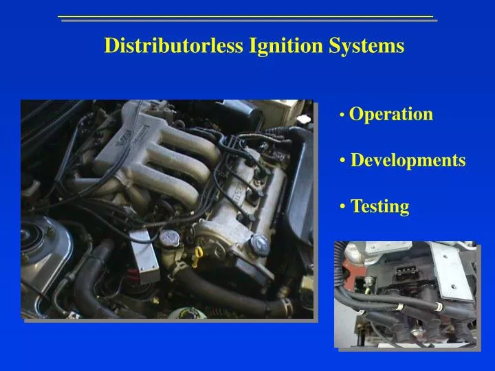
Distributorless Ignition Systems • Operation • Developments • Testing
Distributorless Ignition Systems • The principles of operation are basically no different than those for • distributor equipped electronic ignition systems that began appearing • on American automobiles in 1972. • There are 2 obvious differences: • A DI system does not have a mechanical distributor. • Most DI systems use one coil for every two spark plugs (however • some systems have one coil per cylinder i.e. BMW).
Distributorless Ignition Systems In operation the only major difference is that DI systems fire all of the engines spark plugs in ONE crankshaft revolution, whereas the old mechanical distributor type fires all plugs every TWO crankshaft revolutions. On all four stroke engines, equipped with or with out distributors require TWO crankshaft revolutions (720° travel) for the combustion to occur on each cylinder. On engines with an even number of cylinders, combustion occurs in half of the cylinders in the first revolution (360°) and in the other half in the second half of the revolution. Each cylinder that has combustion in the first revolution has a companion cylinder that fires 360° apart from it during the second revolution.
NGK NGK NGK NGK + Layout ECU ECU Primary Secondary Primary Secondary
Distributorless Ignition Systems In conventional systems the ignition coil is always connected so that the secondary winding side will always be negative. This is done because the electrons readily tend to leave a hot surface much more easily than a cold surface (the outer electrode is much colder because it sinks heat into the cylinder head). Therefore 30% more energy is needed to fire a plug backwards (from the centre electrode). As DIS produces high voltages (40 KV), this eliminates any difficulty in firing the plugs.
+ - BATTERY DISTRIBUTOR CAP STARTER MOTOR 15 NGK 4 IGNITION COIL 1 Conventional System IGNITION SWITCH _ + Terminal 15 + Terminal 1 - _ POINTS CONDENSER
NGK NGK NGK NGK + ECU ECU Primary Secondary Firing 1342 Primary Secondary TDC power TDC exhaust
NGK NGK NGK NGK + ECU ECU Primary Secondary Firing 1342 Primary Secondary
Distributorless Ignition Systems As can been seen from the previous screens, the DI system has 2 secondary terminals that are connected to the spark plugs of companion cylinders. The coil fires both spark plugs at the same time every crankshaft revolution. One of the spark plugs is called TRUE firing, because it occurs during the compression stroke and ignites the mixture. The other plug is called WASTED firing because it occurs on the exhaust stroke.
Distributorless Ignition Systems Primary Secondary NGK NGK Electron Flow - negative to positive _ +
NGK NGK _ + ELECTRON FLOW + TO - NGK NGK Primary Secondary
Distributorless Ignition Systems The arrows on the previous page show the direction of electron flow in the circuit when a spark occurs. It can be seen that the electron path is from the left end (-) of the secondary winding through the centre electrode and then through the head to the outer electrode of the right hand plug. After then jumping over the gap to the centre electrode they flow to the right hand end of the secondary (+) winding. The series connection of the spark plugs causes one of the plugs to always fire in the reverse direction. The wasted firing needs very little energy to bridge the gap due to the lack of pressure in the cylinder, leaving more power for the cylinder under pressure.
Distributorless Ignition Systems Construct the following circuit in Crocodile Clips. It shows very simply how one coil pack operates. Print out your design.
Distributorless Ignition Systems On DIS systems the ECU obtains crankshaft position by the means of an inductive sensor (many systems have a camshaft sensor as a failsafe). PERMANENT MAGNET Crankshaft Sensor SOFT IRON CORE WINDING Camshaft Sensor
Distributorless Ignition Systems The ECU utilises the KNOCK sensor to maximise performance and economy. Knock always occurs soon after TDC and lasts between 3 to 15 ms. Therefore the sensor is only expected to send true knock signals during a small window. Within the window all the signals are processed outside the window they are ignored. Knock Sensor
Distributorless Ignition Systems The D.I.S. system interfaces with two double spark coils as discussed before. An ignition module (trigger box) is fitted below the coil pack. The purpose of the module is to switch the coils on and off at the correct time when it receives a signal from the ECU. This signal from the ECU is a low voltage signal (0.2 - 0.8 volts AC) known as the Electronic Spark Timing (EST) signal.
Distributorless Ignition Systems There are 4 connections to the D.I.S module: 1. Ignition live 2. Earth 3. EST A (cyls. 1 + 4) 4. EST B (cyls. 2 + 3)
Distributorless Ignition Systems Coil Primary Resistance: 0.56 ohms +/- 0.05 ohms Coil Secondary Resistance: 6 kohms +/- 50 ohms When the ECU determines the dwell time the EST signal will turn from low state (0.50v) to a high state (4.9v). After dwell time the EST signal will turn from a high state (4.9v) to a low state (0.5v).
Distributorless Ignition Systems The dwell algorithm of the ECU consists of 2 different modes. In crank mode the dwell time is based upon a fixed number of engine angles as well as battery voltage. In the run mode the dwell time is based upon engine speed and battery voltage. The transition from crank to run mode takes place at 400 rpm.
Distributorless Ignition Systems Systems now use 1 coil per cylinder as in the BMW’s.
Distributorless Ignition Systems Tasks 1. When did electronic ignition systems first start appearing o vehicles? 2. State the advantages of D.I. Systems. 3. State the major differences of D.I. Systems? 4. Draw and label a simple D.I. System. 5. What charge is the secondary winding and why? 6. How much energy is needed to fire the spark backwards? 7. How much voltage does a D.I. System produce? 8. What is meant by the terms Wasted and True firing? 9. Describe the electron flow in a D.I. Circuit? 10. Discuss and produce test procedures on a D.I. System.