Download
1 / 15
190 likes | 1.06k Vues
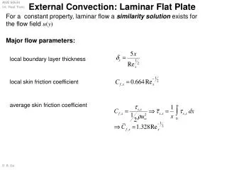
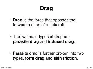
Flat Plate Drag. Drag on flat plate is solely due to friction created by laminar, transitional, and turbulent boundary layers. Flat Plate Drag. Local friction coefficient Laminar: Turbulent: Average friction coefficient Laminar: Turbulent:.

E N D
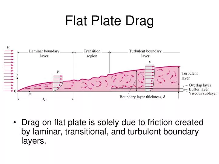
Flat Plate Drag • Drag on flat plate is solely due to friction created by laminar, transitional, and turbulent boundary layers.
Flat Plate Drag • Local friction coefficient • Laminar: • Turbulent: • Average friction coefficient • Laminar: • Turbulent: For some cases, plate is long enough for turbulent flow, but not long enough to neglect laminar portion
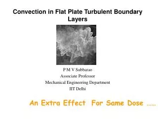
Effect of Roughness • Similar to Moody Chart for pipe flow • Laminar flow unaffected by roughness • Turbulent flow significantly affected: Cf can increase by 7x for a given Re
Cylinder and Sphere Drag • Flow is strong function of Re. • Wake narrows for turbulent flow since TBL (turbulent boundary layer) is more resistant to separation due to adverse pressure gradient. • sep,lam ≈ 80º • sep,lam ≈ 140º
Lift • Lift is the net force (due to pressure and viscous forces) perpendicular to flow direction. • Lift coefficient • A=bc is the planform area
Computing Lift • Potential-flow approximation gives accurate CL for angles of attack below stall: boundary layer can be neglected. • Thin-foil theory: superposition of uniform stream and vortices on mean camber line. • Java-applet panel codes available online: http://www.aa.nps.navy.mil/~jones/online_tools/panel2/ • Kutta condition required at trailing edge: fixes stagnation pt at TE.
Effect of Angle of Attack • Thin-foil theory shows that CL≈2 for < stall • Therefore, lift increases linearly with • Objective for most applications is to achieve maximum CL/CD ratio. • CD determined from wind-tunnel or CFD (BLE or NSE). • CL/CD increases (up to order 100) until stall.
Effect of Foil Shape • Thickness and camber influences pressure distribution (and load distribution) and location of flow separation. • Foil database compiled by Selig (UIUC)http://www.aae.uiuc.edu/m-selig/ads.html
Effect of Foil Shape • Figures from NPS airfoil java applet. • Color contours of pressure field • Streamlines through velocity field • Plot of surface pressure • Camber and thickness shown to have large impact on flow field.
End Effects of Wing Tips • Tip vortex created by leakage of flow from high-pressure side to low-pressure side of wing. • Tip vortices from heavy aircraft persist far downstream and pose danger to light aircraft. Also sets takeoff and landing separation at busy airports.
End Effects of Wing Tips • Tip effects can be reduced by attaching endplates or winglets. • Trade-off between reducing induced drag and increasing friction drag. • Wing-tip feathers on some birds serve the same function.
Lift Generated by Spinning Superposition of Uniform stream + Doublet + Vortex
Lift Generated by Spinning • CL strongly depends on rate of rotation. • The effect of rate of rotation on CD is small. • Baseball, golf, soccer, tennis players utilize spin. • Lift generated by rotation is called The Magnus Effect.