Download
1 / 7
70 likes | 221 Vues
System Block Diagram Mechanical Interface and Component Layout Power Distribution. Major Subsystem Status. RCS. MGF-O. MGF-I. MAST-MGF. PWI-SC. valve module. MAST-SC. ND. ENA. GN2 TANK. MGF-I. MGF-O. PWI-WPT. from/to ADM. MEA1. P. P. P. PWI EWO SORBET AM 2 P MEFISTO-E

E N D
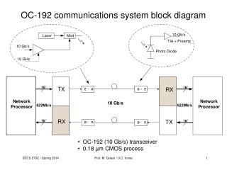
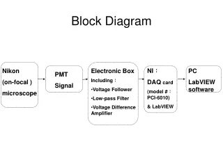
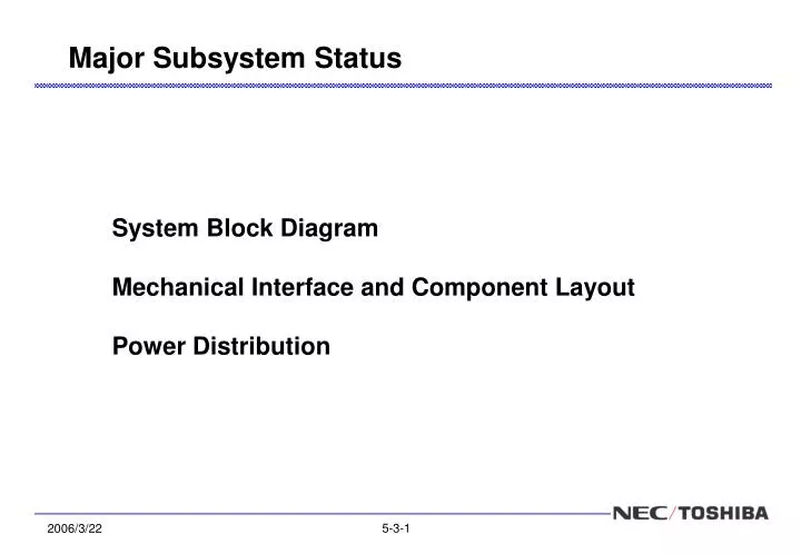
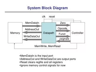
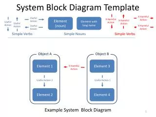
System Block DiagramMechanical Interface and Component LayoutPower Distribution Major Subsystem Status
RCS MGF-O MGF-I MAST-MGF PWI-SC valve module MAST-SC ND ENA GN2 TANK MGF-I MGF-O PWI-WPT from/to ADM MEA1 P P P PWI EWO SORBET AM2P MEFISTO-E MAST/WPT-E from/to APM XSW-C (DPDT) HGA MEA2 thruster module thruster module PWI-MEFISTO TWTA SSC XSW-B XSW-A MSA MDM MDP-1 DPU PSU IPD APM SSAS-S×2 TWTA MIA MDP-2 DPU PSU IPD ADM TLM/CM RF S/S SSAS-E DRU 2ndPWR RJ HEP-i MSASI XSW-C (DPDT) Normal Heater From PCU HEP-e XDIP-A Survival Heater TRP-A DMC SpaceWire (A/B) DR XDIP-B TRP-B PCU MGA SPM MIL-STD-1553B(A/B) PYRO for HGA Latch Mechanism SW & Limiter IG-PS : Signal Separation Connector APR : RF Primary Power for S/S CPM/MPO Electronics CNV2 : SpaceWire DS link BUS-BAT Switch SA SA SEPM/CPM/MPO Power Source : Primary Power To UPG UPG : PSU (other box) BAT : PSU (in the box) To UPG S/S RTN CNV1 SEPM/CPM/MPO Power Source Connector Separation Mechanism SEPM/CPM/MPO Power Source Spin Ejection Mechanism Mechanism System Block Diagram
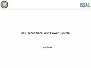
HEP-e MEA1 HEP-i Y (3) MAST-MGF Z X (4) (2) MIA Y ENA (1) (5) Z X Upper Thruster Module(2 places) (6) (8) MEA2 MAST-SC SSAS (7) MSA WPT1 MAST-MGF MGA (after deployment) Lower Thruster Module(2 places) MEFISTO2 MEFISTO1 SSC MSASI MAST-SC WPT2 Component Layout (1/2) Bottom View Top View
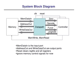
Y Y HEP-e MEA WPT-Pre THR-M HEP-i DMC MDP1 MAST-MGF EPC MDP2 SPM TWT MIA X-TRP1 ENA DRU Tank XSW BAT PCU XDIP MDM Z X Z X XSW V-M SSC XSW MDM-S XDIP MEA CNV-2 X-TRP2 XSW MSASI APR MAST-SC CNV-1 TWT EPC THR-M MSA SSAS-E WPT-Pre SSAS-S Component Layout (2/2) Internal Surface of the Lower Deck, Perspective View from +Z direction. Internal Surface of the Upper Deck, Perspective View from +Z direction.
Geometrical Interface for instruments Updating now Upper Deck Bulkhead Substrate Support Fixture Substrate Lower Deck Substrate Support Fixture will be moved tothe exposed side.It will mitigate restriction on instruments mounting at the corner. Ref. MMO-NT-D05013
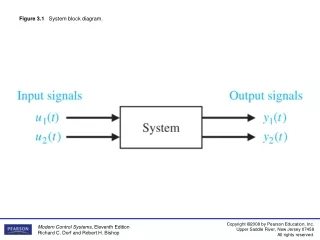
Power Distribution for payloads Issues and possible resolutions> Motors for MEFISTO, WPT, and MAST require 28V, not 50V. External PSU to provide 28V power> Centralized vs. Distributed architecture.It would be too complex to have all of switching functions and secondary power supply functions at the MDP. External PSU for each MPPE and MDM instrument> How to distribute +3.3V to instruments.It would be difficult to provide such a low voltage with good quality from the external PSU. To generate +3.3V by onboard regulator within instruments
PSU MEA-1 PSU MEA-2 PSU MIA PSU MSA PSU HEP-e PSU HEP-i PSU ENA MDP-1 DPU PSU MGF-oe PSU MSASI PSU MDM PSU PSU IPD MDP-2 PWI EWO PWI SORBET PWI AM2P PWI MEFISTO-E MGF-oe MAST/ WPT-E PSU DPU PSU DMC(A) DMC(B) DRU(A) DRU(B) PCD(A) PCD(B) XTRP-A XTRP-B EPC-A EPC-B 10 lines for BUScomp. PCD Alternative Power Distribution Architecture for payloads


![[SERDES Interface Block diagram]](https://cdn1.slideserve.com/3175187/slide1-dt.jpg)