Download
1 / 20
270 likes | 492 Vues
Steel sleepers on bridges. It refers to both channel sleeper and H-Beam sleeper. Design dimensions and sections. Fabrication of steel sleepers and its protective coating should be in conformity with BS-45 of RDSO. For girder, location of steel sleeper should be marked and numbered.

E N D
Steel sleepers on bridges • It refers to both channel sleeper and H-Beam sleeper.
Design dimensions and sections • Fabrication of steel sleepers and its protective coating should be in conformity with BS-45 of RDSO. • For girder, location of steel sleeper should be marked and numbered. • Fabrication of steel sleeper should be location specific considering girder center, top flange cover plates, rivet pitch etc.
Continued.. • In case of bridge on curves, location of sleeper should be marked after taking into account the realigned curve. • In case of transition curves the thickness of pad plates should take care of the cant gradient.
Laying of steel sleeper. • Creep should be adjusted and rails pulled back to position ensuring that no joint is supported. • SSP (sleeper seat painting) and the entire top. • Wherever required cross levels and alignment be corrected in advance. • Single pad plate below sleeper is preferable. • Packing plate can be used if required to adjust parameters. • Pad plates are not required if Neoprene pad is provided to cover the rivet heads.
Spacing • Existing clear spacing is 510 mm. • For all new works it is to be kept at 450 mm. • Channel sleepers should be kept: • Maximum centre to centre spacing at 600 mm. • Clear distance between sleepers at 450 mm. • Clear distance between joint sleepers not > 200 mm.
Inspection. • Thoroughly by ADEN and SSE once in a year by rotation. • SSE (P Way) and SSE S&T once in six months if sleepers are insulated.
Christ Church Crib (CC Crib) • DRG No. RDSO B-1484 • A CC Crib is a hollow frame of size 600x600x1800mm fabricated unit With MS angle 75x75x10mm. • 1800mm length is divided in three parts of 600mm each • Either end parts are provided with diagonal bracing 50x8mm MS flats. • 14mm dia holes are drilled (2 nos. in each 600mm block) for providing 13mm dia bolts
General features • Used in lieu of the permanent bridges structure to ensure uninterrupted traffic • Are designed as simple and light weight structures so as to be handled easily during erection and ensure faster speed of constructions • In past they were designed for stop dead and 8/10 kmphbut now they are being designed for NS 20/30*kmph speed to avoid excessive time loss
General features • Are used in track in following cases • To relieve entire bridge or any part of it for repair work • To provide new opening in embankment • Emergency restoration in case of accident on bridge or wash away of bridges structure due to flood / breaches
Temporary arrangement after washout RH girder on CC crib pier • water may be running • Soil may be wet and/or likely to be wet in future
CC crib fabrication • Important precaution for CC Crib • Steel should conform to IS 2062 GR A • All fillet weld should be 10mm size • Fabrication to be done by qualified welders • All welds be tested using NDT technique • 13 dia bolts and clamps to be provided as per drawing
CC crib staging • These cribs can be used to support RH girders under traffic • Weight of each crib is 187.2 Kg. • To ensure that crib acts as one unit, 13mm dia bolts are used in interior portion of crib and screw clamps on outer periphery • Bottom layer of crib be anchored to base Layer of wooden sleeper using sill type clamp
CC crib staging • CC cribs • Can be used for pier height upto7.8m for spans 12.2m, 18.3m and 24.4m • For 18.3m & 24.4m span RDSO drawing B/1484/Sheet No.1,2,3 • For 12.2m span, RDSO drawing No.B/1486/Sheet No.1,2,3 • For clamps, RDSO drawing No.B/1484/Sheet No.4
R.H.GIRDER • Restricted Head – RH (Reduced Height) Girders are also known as reliving girders or service spans • Design is based on the use of these girders for repairs or rebuilding of arch bridges • As height between rail level to crown is normally 1400mm. Hence height of these girders are kept 840 or 1000mm. So that about 400 to 500mm working space is available
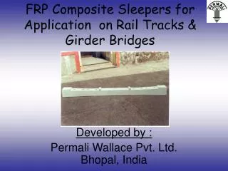
Technology transfer has been done from Tie Tek, USA. • These sleepers are manufactured using recycled material. • This is in lieu of channel sleepers for girder bridges. • Indian railways have begun laying of these sleepers on 10 zones across the country.
The expected life of this sleeper is 40 years. • They are made from cramerrubber, glass reinforcement and fillers, recycled hdpe. • They are not susceptible to rupture, decay or insect infestation.