Download
1 / 33
330 likes | 443 Vues
Integrated Climate Evaluator (ICE) Tracker. ENSC 440 Project Demonstration and Presentation April 23, 2011. Overview. Background Design High Level Details Demonstration Conclusions. The Problem. The Problem.

E N D
Integrated Climate Evaluator (ICE) Tracker ENSC 440 Project Demonstration and Presentation April 23, 2011
Overview • Background • Design • High Level Details • Demonstration • Conclusions
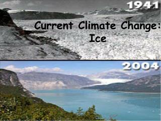
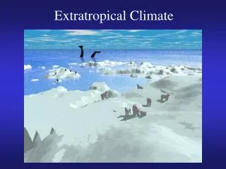
The Problem • Climate change is a controversial issue; the best way to resolve is usually more information • The Arctic is a sensitive environment: tracking ice floes to monitor ice formation and environmental conditions can tell us more about climate change
Possible Solutions • Satellite Photographic Analysis • Unreliable: low level lights in winter • Loss of monitoring during storms • Poor update frequency
Possible Solutions • Unmanned Aerial Vehicle (UAV) Monitoring • Identifying distinct ice features can be difficult • Cannot measure large areas simultaneously • Requires base station throughout season • (expensive)
Possible Solutions • Fixed Monitoring Stations • Can measure secondary data along with position • Groups of pods can measure data simultaneously • Pods need power supplies which can last all winter • Hard to recover pods and new ones must be purchased every year
Our Solution • Autonomous unit that determines its GPS location and takes environmental data • Communicates via Iridium satellite modem hourly, every 30 mins etc. • Self powered (approx. 8 months) • Design challenges: reliability in marine environment, temperature range, power consumption
General Design Considerations • Sustainability – all components RoHS compliant • Reliability • Functional to -20°C • Avoids damage to -40°C • Internal and external PCB • IP-67 standards • Low power components where possible • Usability – system is assembled and calibrated
Design Areas • Mechanical: Enclosure • Conrad Lichota and Gianmarco Spiga • Electronics: Sensors, Communication, Power Control • Brendan Moran and Lydia Zajiczek • Software: Microcontroller • Andrei Simion
Enclosure • Material: 6061 Aluminum • Lightweight • Corrosion-resistant • Easy to machine • Low cost • Alternative is stainless steel or Delrin 12
Enclosure • Main Enclosure Design: • Tube and Caps • Advantages • Threaded rods act as support beams • Easy to machine • Radial O-rings protect interior electronics • Disadvantage • Threaded rods: 6 more holes for leaks 13
Environmental Data • Air temperature/relative humidity • Barometric pressure • Ice temperature/fall through detection • Not implemented for demo: • Heave • Large number of sensors increased complexity • Solution: microcontroller to interface between them
Satellite Communication • Other key requirement: determining its location and communicating it (with other data) to end user • Location:low-cost, low-power GPS receiver • Communication: Iridium modem for satellite communication with end user, set up account and can send message to any email address • Antenna: dual-band antenna with waterproof connector
Power Control • Key goal is to maximize battery life • Power to sensors, GPS, Modem is gated • Separate voltage regulators for standby and active modes • Backup capacitor to supply large currents for data bursts
Microcontroller LPC1769 chosen for development software Free, open source and royalty free operating system Each sensor acquires information in parallel tasks Results are sent to a central task Sensor information is compiled into a message and sent to an email via the Iridium modem 18
Team Dynamics • Tasks allocated/roles assigned according to strengths: • CEO Brendan Moran • COO GianmarcoSpiga • VP Software Andrei Simion • VP Hardware Conrad Lichota • Corporate Secretary Lydia Zajiczek
Team Collaboration Weekly progress meetings throughout the semester Constant communication: lots of emails! (~300) 21
Schedule • Deviation from proposed schedule: extension! • Sources of delay: • External fabrication • Changes requested by client
Lessons Learned Client sponsored project: have to be comfortable with changing specifications External fabrication: have to plan for scheduling mishaps Top-down management: easy to let one person do more work Everyone learning the same things vs. finishing a complex project
Current Status • Have working prototype, have not satisfied all requirements but will produce second prototype that includes • Heave calculation • Fall through detection • Flotation collar
Demonstration • Tests: • Real-time communication • Sensor tests have been performed • Submersion test has been performed
Sources of Information/Acknowledgements Client Pavel Haintz for design requirements, suggestions on materials, electronics Dr. Andrew Rawicz for information regarding reliability in a marine environment Delyane Pleskore for guidance on power control Matthew Asplin for information on end-user requirements
Conclusion Met critical design criteria: autonomous, determines location, takes data, communicates it Project sounded simple but actually had a high degree of complexity and subtlety Completing a complex project successfully vs. everyone learning Next step: improve and expand current design for possible sale to end user
References • Video reference • http://www.youtube.com/watch?v=W0F-RmOswOs • Image references • http://www.cleveland.com/nation/index.ssf/2010/01/spy_satellites_are_now_being_u.html • http://www.xyberlog.com/2008/07/01/we-will-buy-satellites-for-spying-our-enemies-pentagon/ • http://earthsky.org/biodiversity/betsy-weatherhead-monitors-arctic-wildlife-with-unmanned-aircraft • http://www.keytometals.com/Article99.htm • Hands photo credit: Steven Bridge
Possible Reliability Problems • Single point of failure: real-time clock (RTC) of microcontroller • End cap may be susceptible to water ingress (add isolation) • We cannot test lifetime in our timeframe