Download
1 / 35
370 likes | 548 Vues
Coherent phase shift keying. In coherent phase shift keying different phase modulation schemes will be covered i.e. binary PSK, quadrature phase shift keying and M- ary PSK Binary PSK will be studied in the next slides. Binary Phase shift keying.

E N D
Coherent phase shift keying In coherent phase shift keying different phase modulation schemes will be covered i.e. binary PSK, quadrature phase shift keying and M-ary PSK Binary PSK will be studied in the next slides
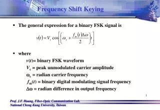
Binary Phase shift keying In a coherent PSK system the pair of signals and are used to represent binary logics 1 and 0 respectively
Binary Phase shift keying Where , and is the transmitted signal energy per bit The carrier frequency is selected such that so that each bit contains an integral number of cycles From the pair of symbols and we can see only one basis function (carrier) is needed to represent both and
Binary Phase shift keying The basis function is given by Now we can rewrite and on the interval
Signal constellation for binary Phase shift keying In order to draw the constellation diagram we need to find the projection of each transmitted symbol on the basis function The projection of the logic (1); ; is given by The projection of the second symbol on the basis function is given by
Signal constellation for binary Phase shift keying If we plot the transmitted symbols for BPSK we may got the following constellation diagram
Error probability of BPSK In order to compute the error probability of BPSK we partition the constellation diagram of the BPSK (see slide 28) into two regions If the received symbol falls in region Z1, the receiver decide in favor of symbol S1 ( logic 1) was received If the received symbol falls in region Z2, the receiver decide in favor of symbol S2 (logic 0) was received
Error probability of BPSK-Receiver model The receiver in the pass band can be modeled as shown The received signal vector
Error probability of BPSK The observable element (symbol zero was sent and the detected sample was read in zone 1) is given by
Error probability of BPSK To calculate the probability of error that symbol 0 was sent and the receiver detect 1 mistakenly in the presence of AWGN with , we need to find the conditional probability density of the random variable , given that symbol 0, was transmitted as shown below
Error probability of BPSK The conditional probability of the receiver deciding in favor of symbol 1, given that symbol zero was transmitted is given by
Error probability of BPSK By letting the above integral for can be rewritten as
Error probability of error In similar manner we can find probability of error that symbol 1 was sent and the receiver detect 0 mistakenly The average probability as we did in the baseband can be computed as This average probability is equivalent to the bit error rate
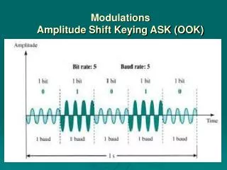
Generation of BPSK signals To generate a binary PSK signal we need to present the binary sequence in polar form The amplitude of logic 1 is whereas the amplitude of logic 0 is This signal transmission encoding is performed by using polar NRZ encoder
Generation of BPSK signals The resulting binary wave and the carrier (basis function) are applied to product multiplier as shown below
Detection of BPSK signals To detect the original binary sequence we apply the received noisy PSK signal to a correlator followed by a decision device as shown below The correlator works a matched filter
Power spectra of binary PSK signals The power spectral density of the binary PSK signal can be found as described for the bipolar NRZ signaling (see problem 3.11 (a) Haykin) This assumption is valid because the BPSK is generated by using bipolar NRZ signaling
Power spectra of binary PSK signals The power spectral density can be found as
Quadrature phase shift keying QPSK In quadrature phase shift keying 4 symbols are sent as indicated by the equation Where ; is the transmitted signal energy per symbol, and is the symbol duration The carrier frequency is for some fixed integer
Signal space diagram of QPSK If we expand the QPSK equation using the trigonometric identities we got the following equation Which we can write in vector format as
Signal space diagram of QPSK There are four message points defined by According to this equation , A QPSK has a two-dimensional signal constellation (i.e. or two basis functions)
s4 s1 s3 s2 Signal space diagram of QPSK 2 (01) (11) 1 (10) (00)
s4 s1 s3 s2 Signal space diagram of QPSK with decision zones 2 Z3 Z4 (10) (11) Z1 1 Z2 (10) (00) The constellation diagram may appear as shown below
Example Sketch the QPSK waveform resulting from the input binary sequence 01101000 solution
Error probability of QPSK In coherent QPSK, the received signal is defined by Where is the sample function of AWGN with zero mean and power spectral density of
Error probability of QPSK The observation vector has two elements, and defined by
Error probability decision rule If the received signal point associated with the observation vector falls inside region , the receiver decide that was transmitted Similarly the receiver decides that was transmitted if falls in region The same rule is followed for and
Error probability of QPSK We can treat QPSK as the combination of 2 independent BPSK over the interval since the first bit is transmitted by and the second bit is transmitted by Probability of error for each channel is given by
Error probability of QPSK If symbol is to be received correctly both bits must be received correctly. Hence, the average probability of correct decision is given by Which gives the probability of errors equal to
Error probability of QPSK Since one symbol of QPSK consists of two bits, we have E = 2Eb The above probability is the error probability per symbol With gray encoding the average probability of error per bit Which is exactly the same as BPSK
Error probability of QPSK summery We can state that a coherent QPSK system achieves the same average probability of bit error as a coherent PSK system for the same bit rate and the same but uses only half the channel bandwidth
Generation and detection of QPSK • Block diagrams of (a) QPSK transmitter and (b) coherent QPSK receiver.