Download
1 / 29
290 likes | 439 Vues
JLC CCD Vertex Detector R&D. Y. Sugimoto KEK 2003. 8. 19. Members. KEK A. Miyamoto, K. Nakayoshi, Y. Sugimoto, H. Yamaoka Niigata U. K. Fujiwara, G. Iwai, Y. Onuki, N. Tamura, H. Takayama Saga U. T. Kuniya, K. Nakamura, K.D. Stefanov, T. Tsukamoto

E N D
JLC CCD Vertex Detector R&D Y. Sugimoto KEK 2003. 8. 19
Members • KEK A. Miyamoto, K. Nakayoshi, Y. Sugimoto, H. Yamaoka • Niigata U. K. Fujiwara, G. Iwai, Y. Onuki, N. Tamura, H. Takayama • Saga U.T. Kuniya, K. Nakamura, K.D. Stefanov, T. Tsukamoto • Tohoku U. T. Nagamine, Y. Shirasaki • Tohoku Gakuin U. K. Abe • Toyama College T. Aso of Maritime Tech. Red names: Graduated or left ( 4 Ms and 1 D)
Contents • Introduction • Possible Options • Why CCD? • R&D Program • What has been achieved? • What has been left to be done? • Future Prospects
Possible Options • Candidates for Vertex Detectors at LC • Silicon Strip Detector --- Occupancy • Hybrid Active Pixel Sensor --- Thickness • Charge Coupled Device (CCD) • Monolithic Active Pixel Sensor (CMOS) • Other New Ideas (DEPFET, SOI, etc.)
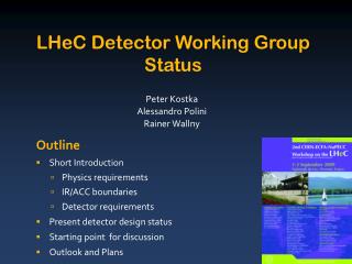
MIP source top gate drain clear bulk n+ p+ p+ n+ n+ p n s i internal gate x a + - - y - - - r t - - e + m - m y s + - n + - p+ rear contact DEPFET ~1µm 50 µm
Why CCD? • Mission: Show a design by the end of 2000 (ACFA Report) • Structure of CCD • Diffusion of electrons in epitaxial layer • Key of excellent spatial resolution for CCD & CMOS pixel sensors • Takes time to diffuse d = sqrt(Dt) ~ 6mm @ t=10ns • OK for JLC/NLC (Fully depleted CCD at TESLA) • CCD has simple structure • Large area sensor • High yield CCD is the most feasible option
CCD MAPS HAPS DEPFET Resolution AAA AAA A A Thin material AAA AAA C AA Rad. Hardness A(?) AA AAA AAA(?) Large wafer AAA ? ? ?
R&D Program • Design Criteria : “The Highest Vertex Resolution with Technical Feasibility” • High spatial resolution of the sensor • Minimize multiple scattering Thin wafer • Close to the IP Radiation Hardness • Room temperature operation, if possible
Spatial Resolution • Beam Tests in ’97 and ’98 • KEK PS T1 beam line • 0.5 – 2.0 GeV/c pion • 4-CCD Telescope • CCD Samples: HPK 24 mm2 10/50 mm epi. EEV 22 mm2 20 mm epi. • Resolution better than 3mm(r.m.s) was obtained Excellent spatial resolution of CCD has been demonstrated.
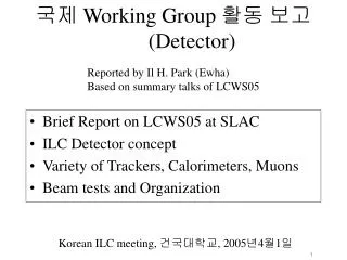
Spatial Resolution (Cont.) • Resolution Study with Laser Beam Scanner (Niigata U.) • Beam spot size: 2mm • l=532 nm / 1064 nm • IR(1064nm) Laser simulates MIP • Quick study possible • Study of charge spread
Laser Scanner 532 nm 1064 nm
Thin Wafer • CCD has sensitive thickness ( = epitaxial layer thickness) of ~20mm Can be thinned down to 20mm if mechanically OK • Several ideas: • Thin wafer stretched by tension • Thin wafer glued on Be support • Partially thinned wafer --- Our study
Partially Thinned Wafer • Picture Frame Type • Sample wafer : Back illumination CCD • System for flatness measurement constructed • Non-flatness has been measured Poor Flatness
Honeycomb & Grid Type Average thickness = 76 mm = 100 mm (including edge) ~0.1% X0 ANSYS analysis: material~1/3 rigidity~1/3 Simple plate: thickness 1/3 rigidity 1/27 Models for ANSYS
Radiation Hardness of CCDs • Radiation Damage on CCDs • Surface Damage: Charge build-up in SiO2 and SiO2-Si interface by dE/dx • Increase of surface dark current • Shift of operation voltage (Flat-band Voltage Shift) • Bulk Damage: Displacement in lattice • Increase of bulk dark current • Charge Transfer In-efficiency (CTI)
Dark Current and Flat-band Voltage Shift HPK S5466 irradiated with 10mCi Sr-90 b-source No bias during irradiation Biased during irradiation
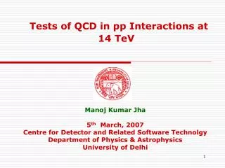
Study of CTI • HPK S5466 and EEV CCD02-06 irradiated with Sr-90 b-source and Cf-242 n-source • Read-out cycle = 3 sec (250 kHz) • CTI looks decreasing at higher temperature because of increase of dark current which fill-up the traps. (EEV CCD showed much worse CTI due to less dark current) NOT expected at JLC where Tcyc=6ms and much less dark current Fat-zero charge injection (~1000 e) is desirable HPK S5466
Other CTI Improvements • Notch Channel CCD • High speed readout : Horizontal CTI is expected prop. to 1/f
Conclusion from Radiation Damage Study • Surface damage NOT problem in MPP mode operation and 6ms cycle time • CTI study + Beam Background Simulation CCD can be used for 3 years with - B=2T, R=24mm - JLC A-Option - Notch channel - Fat-zero charge injection - assuming that effect of H.E. electrons is 10 times stronger than Sr-90 b-source BUT large ambiguity in E-dependence of electron damage and neutron background level.
Model Calculation of NIEL • Bulk damage is thought to be proportional to Non-Ionizing Energy Loss (NIEL) Sr-90 LC pair background
R&D Items left to be done • Spatial Resolution • Study of resolution of radiation-damaged CCD • Study of charge diffusion in epi. layer • Thin Wafer • Try to get sample wafers of Honeycomb/Grid type
R&D Items left to be done (Cont.) • Radiation Hardness Study • Study of energy dependence of bulk damage • High energy (150MeV) electron irradiation at Tohoku Univ. • Study of characteristics of irradiated CCDs • Id vs. Temp • Flat-band Voltage Shift • CTI vs. Temp • CTI vs. Readout frequency cPCI DAQ System • CTI vs. Fat-zero charge: Injection of controlled amount of charge • CTI vs. clock pulse width/height • Annealing/anti-annealing
R&D Items left to be done (Cont.) • Simulation studies concerning Vertex det. • Background study using Full Simulator (JIM, JUPITER) • Crossing angle: 7 mrad 20 mrad • Physics study using Quick Simulator • Physics and Detector study using Full Simulator
Future Prospects • FY2003-FY2004 • Continue jobs left to be done Find out the best design and operating condition of CCD vertex detector • Prepare for the next step • Conceptual design of prototype ladder (with HPK) • Find out the financial source • Japan-US, KAKENHI, or KEK GAISAN-YOUKYU ? • FY2005- The Next Step • Construction of prototype ladder
Future plan in FY2005~ • Custom made CCDs with • Reduced material ( honeycomb type? ) • > 20MHz readout speed • Multiple readout nodes • Notch structure • Charge injection capability • Readout by ASIC with multi-channel CDSs, Amplifiers, ADCs, and a Multiplexer
Multi-Thread CCD • Normal CCD: Many V-shifts Sig. Loss • CPCCD: Limited space for r.o.elec. • Multi-port CCD with few tens of V-shifts : MTCCD • Can be used as a high speed CCD camera • HPK says “Challenging but not impossible”
Conclusion • Feasibility of the baseline design of a CCD Vertex Detector has been established. • R=24, 36, 48, 60 mm • s < 4 mm • Thickness = 300 mm /layer • sb = 7 + 20/(pbsin3/2q) mm • To get better performance, studies to get • Rin < 24 mm ( Radiation hardness) • Thickness << 300 mm will be continued. A milestone is sb = 5 + 10/(pbsin3/2q) mm • Eventually, we have to make a prototype ladder to demonstrate the required performance. ( need \)
Appendix • Situation in Europe • LCFI Group (UK) : R&D for Column Parallel CCD • 2.26M£ from PPARC (UK): 2002, 2003, 2004 (3y) • Approved as DESY PRC R&D 01/01 • MAPS Group (CMOS) • DESY PRC R&D 01/04 • DEPFET • DESY PRC R&D 03/01 • SiLC, CALICE, TPC, -----, submitted proposals to DESY PRC