Download
1 / 15
840 likes | 3.25k Vues
Four Point Probe. Procedure for Pro4 using Keithley. Overview. What is Four Point Probing How the system works Pro 4 Set Up Simple Calculations behind Four Point Probing Procedure for using Pro4. What is Four Point Probing.

E N D
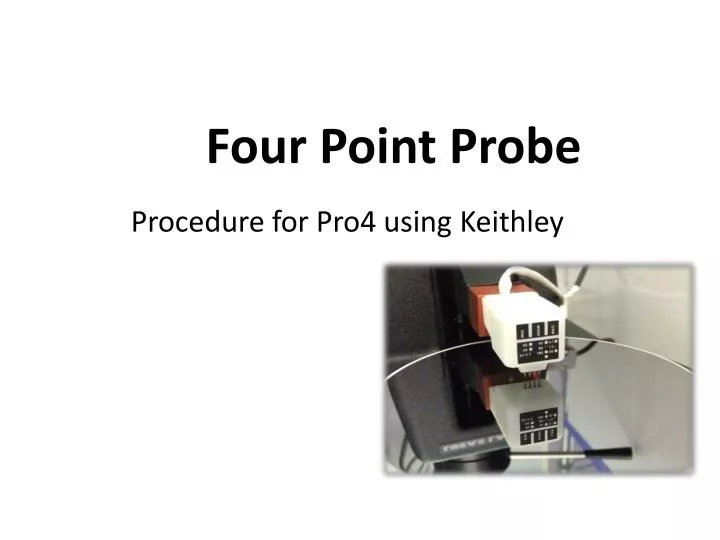
Four Point Probe Procedure for Pro4 using Keithley
Overview • What is Four Point Probing • How the system works • Pro 4 Set Up • Simple Calculations behind Four Point Probing • Procedure for using Pro4
What is Four Point Probing • Four Point Probing is a method for measuring the resistivity of a substance. • Impurity concentrations can be estimated from the resistivity
Resistivity vs Sheet Resistance • Bulk or volume resistivity (r) is measured in ohms-cm • Independent of sample size or shape • Sheet resistance (rs)is measured in ohms-per-square • Can be used to measure the value a resistor in a IC
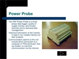
Pro-4 Set Up The 4 point probing setup consists of 3 key components • Pro-4 probing station from LUCAS LABS with 4 point probe head • KEITHLEY 2400 power/source meter • Computer with Pro4 software and interface Source Meter Pro-4 Software Probing Station The 4 point probing setup can measure resistivity or the thickness of a film. But, either one has to be known.
Resistivity Probe Stand Contact Lever Probe head electrical connection Probe Head Mounting Chuck (Aluminum base with Teflon surface
How the system works • Current is passed through the two outer probes • Voltage is measured between the two inner probes • Read and record both current and voltage values from the Keithleysource meter • Sheet Resistance is measured using (V/I) and k • V = volts, I = Amps (convert current reading to amps) • k=constant factor = to 4.53 when the wafer diameter is much greater than the probe spacing – typical for wafers • Sheet resistance (rs) = (k)(V/I)= ohms/square
For the bulk resistivity of a wafer • The thickness of the wafer/film must be known – use calipers or micrometer block to measure the wafer thickness • Convert caliper reading in mm to um (microns) • Resistivity of wafer will be shown on the computer screen • There is a second k factor but for our work this k factor is not a factor and can be ignored (typically >.995)
To measure the thickness of a waferUse a caliper or the micrometer stage shown below To turn on, press and hold the right button To turn off, press and hold both buttons The reading on the screen is in mm – a reading of .400mm = 400 microns (um)
Procedure for using the Pro-4 Enter thickness in microns (um) as measured
Procedure for using the Pro-4 Choose either single or multiple readings per wafer. Load the wafer under the 4 point probe head and lower the head using the handle
Procedure for using the Pro-4 Lower the probe heading using the contact lever until the computer screen shows a measurement taking place. Once completed, the screen will show the resistivity and V/I Record resistivity in ohm-cm as shown on the screen
Saving the data • After the measurement is completed, the resistivity at each location will be displayed on the left hand side of the screen. • When all the points are tested, the data can be saved and read using excel
Summary • The Pro-4 can be used to measure resistivity or the thickness. But, either one has to be known. • Typically the thickness of the wafer can be measured • The # of points to be tested and the shape of the sample can be selected. • A single point or multiple points on the sample can be tested to obtain the average resistivity. • The resistivity is automatically displayed when the thickness is entered. • Additional information is also displayed including V/I
Sample Wafer CalculationsUsing voltage and current measurements • A current of 1.0 mA is passed through the wafer and a voltage reading of 0.030 v is noted. I = 1.0 MA = .001 amp • V/I = .030 v/.001A = 30 ohm • rs = (V/I) k = (.030/.001)(4.53) = (30)(4.53) = 135.9 ohms/square • The wafer is measured as 0.40 mm = .04 cm • r = (135.9)(.04cm) = 5.43 ohm-cm