Download
1 / 27
270 likes | 536 Vues
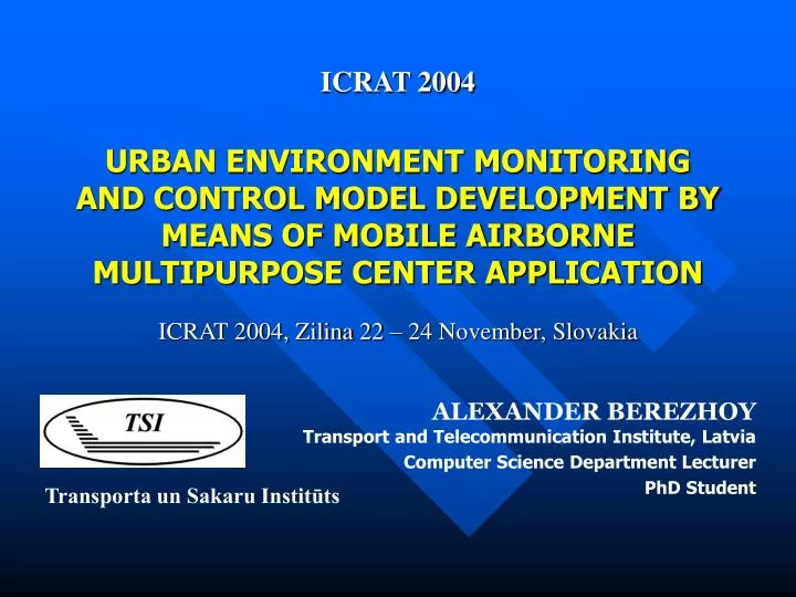
ICRAT 2004. URBAN ENVIRONMENT MONITORING AND CONTROL MODEL DEVELOPMENT BY MEANS OF MOBILE AIRBORNE MULTIPURPOSE CENTER APPLICATION. ICRAT 2004, Zilina 22 – 24 November, Slovakia. ALEXANDER BEREZHOY Transport and Telecommunication Institute, Latvia Computer Science Department Lecturer

E N D
ICRAT 2004 URBAN ENVIRONMENT MONITORING AND CONTROL MODEL DEVELOPMENT BY MEANS OF MOBILE AIRBORNE MULTIPURPOSE CENTER APPLICATION ICRAT 2004, Zilina 22 – 24 November, Slovakia ALEXANDER BEREZHOY Transport and Telecommunication Institute, Latvia Computer Science Department Lecturer PhD Student Transporta un Sakaru Institūts
BALLOONS – AN IRREVOCABLY LEFT VESTIGE!? Regardless of external archaistic view and functioning principles, dirigible balloons and airstats possess some unique features that opens new opportunities for its future application
WAITING FOR A SECOND LIFE - PERSPECTIVES “…For creation of a network of broadband access in region with diameter of scope about 700 km, in 1999 by Sky Station company it has been developed a drop-shaped dirigible balloon filled with helium, 157 m length and diameter of 62 m. It could be located at a height of about 21 km, forming the necessary capacity for the wind stream resistance that is appreciable enough at these heights though the air density is 14 times lower, than at a surface level…”
TASK 1 EXAMPLE: THE NEED TO IMPLEMENT THE URBAN TRANSPORT CONTROL SYSTEM IN RIGA • High density of the transport streams • Comparatively low driving speed • Frequent traffic congestions • Significant overload of the road network • Presence of the big transit share through city • Difficulties in driving because of wrong car placement for parking • The public transport does not cope well with passenger traffic volumes and couldn’t be considered as a worthy alternative to private transport means
POSSIBLE WAYS OF SOLVING THEPOINTED PROBLEMS • Reduction of transport streams attraction by means of putting restrictions on construction of business infrastructure and trading & serving spheres objects • Rearrangement of some establishments from the central part of city • Construction of multi-storey parking buildings and removing of street parking placements • Restriction for entrance of transit transport inside the city • Introduction of the automatedurban traffic streams control system with the SATELLITE NAVIGATION SYSTEM application
Data Storage Feedback Control GATHERING DATA: MEASUREMENT TECHNIQUES • Direct measurements • Indirect measurements Image Processing Monitoring Gauges Mobile Objects Traffic Detection Systems Data Processing
SELECTION OF REMOTE VEHICLE DETECTION SYSTEM A group of experts assigns a set of, importance weights to the attributes, w = {w1, w2, …, wn}. Then the most preferred alternative, A*, is selected such thatwhere xij is the outcome of the ith alternative about the jth attribute with a numerically comparable scale.
SELECTION RESULTS FOR TRAFFIC DETECTION SYSTEMS WINNERS: • Video Detection Systems • Laser-based Systems • Radar Tracking Systems On the same time it is also possible to take the benefit of active response systems usage
LOCATED EQUIPMENT FOR GATHERING, PROCESSING AND TRANSFER OF INFORMATION
SYSTEM APPROACH: COMMUNICATION ARCHITECTURE FOR AIRBORNE MULTIPURPOSE CENTER
TASK 2 EXAMPLE: INCRESEANIG THE ACCURACY OF POSITIONING FOR TRANSPORT MEANS • Stationary gauges for defining a location (video detection systems, microwave systems, laser-based systems etc.) • Portable systems of navigation (ETAK, the Autonavigator, etc.) • Radiowave systems • Radar-tracking systems • Radionavigation systems • Satellite navigation (NAVSTAR, GLONASS, GALLILEO) • Radiodirection finding (Quiktrack, etc.) TRAFFIC NAVIGATION SYSTEMS:
BENEFITS OF SATELLITE NAVIGATION IN URBAN ENVIRONMENT CONDITIONS • Possibility to correlate coordinate of the consumer with time coordinates • Integrity of the received information (the information “is stacked" in one information package, which can be subsequently processed in urban traffic control center) • High reliability and accuracy levels of the obtained data • Almost all the late produced transport means are equipped with satellite navigation receivers
MOBILE OBJECT CONTROL WITH GLOBAL NAVIGATION SATELLITE SYSTEMS At present, there are many companies in the world that develop and produce similar systems (VIALIS, ACIS, ELTRA group, etc.). As an example, the system of company ACIS - BusNet is represented. The given system is a control system for city public transport and is used in many cities of Europe.
2 MAJOR TYPES OF SATELLITE POSITIONING ERRORS IN A CITY BOUNDRIES 1. MULTIPATH ERROR Refractions from buildings, constructions, causes an error ~0.6-1.2 m The given type of mistakes cannot be avoided, since GPS receiver perceives refracted signal as a true.
sm sp . = GDOP “Preferable” geometry Positioning accuracy Pseudo-range error Pseudo-range measurements accuracy Geometric factor Small errors ellipse (GDOP) “Unacceptable” geometry Preferable GDOP (an ideal case): One satellite in the zenith, three above horizon with a difference in an azimuth of 120 degrees Average value GDOP = 2,5 Pseudo-range error Large errors ellipse 2.AN INFLUENCE OF GEOMETRIC FACTOR ON THE ACCURACY OFGNSS
POSITIONING ACCURACY IMPROVEMENT METHOD The technology of differential GPS (DGPS) is based on use of the second receiver established in a point with beforehand known coordinates. It constantly broadcasts adjusting signals which are integrated with the data broadcast from satellites.
POSSIBLE SOLUTIONS FOR DIFFERENTIAL GPS IMPLEMENTATION • Transfer of RTCM amendments with the assistance of geostationary satellites (Omnistar, Starfix, Seastar) • Amendments transfer using a subcarrier frequency in the FM range • Installation of one DGPS station and transfer of amendments to GSM environment through the channels of mobile communication • Construction of the network of differential amendments stations
TASK 2 EXAMPLE: USING THE AIRBORNE PLATFORM FOR DIFFERENTIAL CORRECTION STATIONS ACCOMODATION It is possible to avoid both types of errors – multipath error and influence of geometric factor and make it in a more cost-efficient way!
CONCLUSION • Accommodation of key monitoring and control elements over an urban environment conditions on a platform of “aeroelastic mean” has been offered • The prototype of services structure has been developed • A selection task for remote vehicle detection and monitoring system has been solved • The analysis of conditions for differential correction system allocation has been carried out • Communication architecture for the airborne multipurpose center has been proposed
THANK YOU FOR ATTENTION! ALEXANDER V. BEREZHOY Ph.: +371 9110030 Fax: +371 7100535 E-mail: avb@tsi.lv