Download
1 / 28
280 likes | 289 Vues
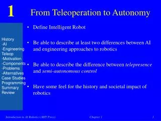
Migration from Teleoperation to Autonomy via Modular Sensor Bricks. ROSELYNE BARRETO FALL 2005 Midterm presentation Imaging, Robotics, and Intelligent Systems Laboratory Department of Electrical and Computer Engineering, The University of Tennessee, Knoxville, TN. OUTLINE. Task1: Thesis

E N D
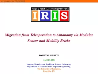
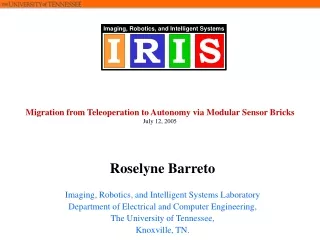
Migration from Teleoperation to Autonomy via Modular Sensor Bricks ROSELYNE BARRETO FALL 2005 Midterm presentation Imaging, Robotics, and Intelligent Systems Laboratory Department of Electrical and Computer Engineering, The University of Tennessee, Knoxville, TN.
OUTLINE • Task1: Thesis • Task 2: Fencing Implementation • Task 3: Primitive Driver • Task 4: Reverse Engineering of ANDROS II • Future Work
THESIS • Chapter 1: Introduction • Overview • Motivation • Applications • Contributions • Organization of the thesis
Original OCU Teleoperation Original OCU Computer Interface Robot Computer Integration Sensor Bricks Autonomy Mobility Bricks THESIS • Chapter 1: Introduction • Overview: This section generally describes the concept of the thesis
THESIS • Chapter 1: Introduction • Motivation: This section goes more in details about the motivation behind the idea. • Keeping the operator in the loop for safety reason • Adding Modularity and Flexibility: Being able to add sensors without major hardware changes to the original robust commercial robot • Using those modular sensor to acquire some autonomy without being restricted to any specific application
THESIS • Chapter 1: Introduction • Applications: This presents the potential need for this project • DOE: chemical safety, nuclear safety and hazardous waste transport. NNSA facilities security (Fencing) • ARC: autonomous data collection and fusion for simulation • Scouting missions for the CST for example • Vehicle Inspection illustrate points such as reachability and complete scrutiny of the vehicle (different sensors reveal additional complementary information)
Teleoperation Original OCU Computer Interface Computer Integration Sensor Bricks Original OCU Autonomy Mobility Bricks Robot THESIS • Chapter 1: Introduction • Contributions
THESIS • Chapter 1: Introduction • Organization of the thesis (TOC) • This chapter is mainly written I need to insert pictures and diagrams and rewrite the organization as the thesis develops
Mobility Brick Sensor Brick Sensor Brick Sensor to Processor Processor Sensor to Processor Processor Processor to Processor Mobility Brick Processor Mobility Brick Processor to Mobility Processor to Mobility Virtual Bricks Mobility and Sensor Bricks Communication Communica tion Mobility Sensor Pre-processing Pre-processing Power Power FENCING • Implement an autonomous fencing function • Configuration of mobility and sensor bricks Sensor Brick
dwall y Wall dview θ R π/2 - θ Robot view θ R Robot Robot θ dmax Top View of System Side View of System FENCING • Implementing an autonomous fencing function x Note: • cos(θ) = dview/2 dmax; sin(θ) = dwall/2dmax; maximize both and θ = 45 deg. • I will assume that the obstacle in front of the robot are at the same height as the sensor and sweep horizontally
Get Info from Sensor Compute YYdiff YYdiff > TH Turn Left |YYdiff| < TH YYdiff < - TH Turn Right Yes Go Forward FENCING • Implementing an autonomous fencing function y RightY YYdiff Wall LeftY θ θ R x Robot θ Top View of System Flowchart while there are no obstacles too close to the robot
PRIMITIVE DRIVER • Migration from Teleoperation to Autonomy using sensor bricks • Keep the OCU and when the robot is on autonomous mode, the same computer (server) controls the robot for safety reasons • The Server puts information on the network and the Client picks up some information • For several robots, every robot receives a message and decide whether to process it or not
Client Server Transition from teleoperated robot to mobility brick 802.11 RS 232 802.11 RS 232 Communi- cation Pre- processing Mobility Main Control Power PRIMITIVE DRIVER • First step remove the RS 232 communication (Add on board computer)
Mobility Brick 1 PRIMITIVE DRIVER • First step remove the RS 232 communication (Add on board computer) • At this point it is an independent subsystem, the operator can log on to the computer and drive the robot – Remote Log in: Not autonomous
OCU or Server Client PRIMITIVE DRIVER • One server; several clients; The Server puts information on the network and the Client picks up some information and decide whether to process it or not
JAUS Message Header Format PRIMITIVE DRIVER • Decide on the common message format to follow for all the robots • ANDROS: Subsystem 01, node 20, component 33 (primitive driver) and instance 01. ( Additional bytes: size, sequence, priority…)
JAUS defined Messages Primitive Driver Actuator commands PRIMITIVE DRIVER • At this point I have implements the Server that processes the range data and sends it back to the robot • I need to write the client which receives general messages, checks whether it is the right destination before processing • As soon as this part is implemented, I will be able to test the Fencing function using temporary mobility hardware
ANDROS II MAPPING • I have mapped and decoded ANDROS 2 • The results are what we expected: • Longer string (more capabilities) • From 21 characters to 35 characters • Faster baud rate (faster robot) • From 1200 to 9600
Front/Rear tracks Torso Vehicle Drive Mobility Brick 2 • Most function are still aligned • One additional function (wrist pitch) 0A000C2000908D80C0Æññ 0A00182000907F7F3F0000FFFF02CF02þññ Check sum works the same
ANDROS II MAPPING • Despite the similarities in the functionality of the two robots, the F6A is still not currently responding to the program • Series of tests have been conducted to identify the problem both in the program and in the hardware of the system
ANDROS II MAPPING • Software tests: to exclude the software as the cause of the problem, the code • Does Not generating the strings, the testing strings are directly copied and pasted into the code • Added constant signal at one point to check if that was the problem • Connected the COM ports of the computer to check that the computer is indeed sending the correct strings at the correct baud rate
ANDROS II MAPPING • Hardware tests involve two main questions, are the strings getting to the robot? Is there a handshake mechanism between the OCU and the robot • Wire diagram indicates that we have the right receive and ground • One test verified that we have the right input at the robot and that there is no other wire involved in the transmission, there is no feedback from the robot
OCU Robot GND GND TX RX ANDROS II MAPPING • Hardware tests involve two main questions, are the strings getting to the robot? Is there a handshake mechanism between the OCU and the robot Hardware Test on the F6A
8V - 8V ANDROS II MAPPING • Somehow the robot recognizes the original OCU. In order to minimize the connection issues I reformatted the wireless units to transmit at 9600 baud rate and this still did not solve the problem • The next step was to look at the signals emitted from the OCU on an oscilloscope
ANDROS II MAPPING • The fact that this OCU is sending voltages between 8 and -8V may be the problem as the computer can only send 0 to fives volts • The computer may be able to read the high and low from the OCU however when it reproduces it the ANDROS does not recognizes the highs and the lows • More testing will reinforce this first conclusion
CONCLUSIONS • Chapter 1 is written except for diagrams and pictures insertion. The organization of the thesis will also be rewritten as the document involves • The server is written for ANDIBot1 • A first version of the client was written without common messages • Several software and hardware tests were conducted on ANDROS 2
FUTURE WORK • Edit the literature review for chapter 2 • Fit the report previously written into my thesis • Add new elements such as JAUS pertinent to the thesis • Write the client for ANDIbot1 (primitive driver) • This step will allow testing of the first version of the fencing algorithm • Before claiming that I have narrowed down the problem with ANDROS 2, take the first OCU and look at the kind of voltages that it is emitting • This test will clarify the next step to take
THANK YOU !!! Questions?