Download
1 / 78
800 likes | 988 Vues
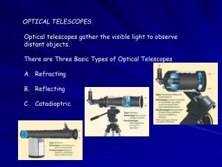
Instrumentation Concepts Ground-based Optical Telescopes. Keith Taylor (IAG/USP) Aug-Nov, 2008. IAG-USP (Keith Taylor). Aug-Sep, 2008. Optical Basics (appreciative thanks to USCS/CfAO). Adaptive Optics. Turbulence changes rapidly with time. Image is spread out into speckles.

E N D
IAG/USP (Keith Taylor) Instrumentation ConceptsGround-based Optical Telescopes Keith Taylor (IAG/USP) Aug-Nov, 2008 IAG-USP (Keith Taylor) Aug-Sep, 2008
Optical Basics (appreciative thanks to USCS/CfAO) Adaptive Optics IAG/USP (Keith Taylor)
Turbulence changes rapidly with time Image is spread out into speckles Centroid jumps around (image motion) “Speckle images”: sequence of short snapshots of a star, using an infra-red camera
tropopause 10-12 km wind flow over dome boundary layer ~ 1 km Heat sources within dome Turbulence arises in many places stratosphere
Schematic of adaptive optics system Feedback loop: next cycle corrects the (small) errors of the last cycle
Frontiers in AO technology • New kinds of deformable mirrors with > 5000 degrees of freedom • Wavefront sensors that can deal with this many degrees of freedom • Innovative control algorithms • “Tomographic wavefront reconstuction” using multiple laser guide stars • New approaches to doing visible-light AO
Ground-based AO applications • Biology • Imaging the living human retina • Improving performance of microscopy (e.g. of cells) • Free-space laser communications (thru air) • Imaging and remote sensing (thru air)
IAG/USP (Keith Taylor) Aberrations in the Eye … and on the telescope
Why is adaptive optics needed for imaging the living human retina? • Around edges of lens and cornea, imperfections cause distortion • In bright light, pupil is much smaller than size of lens, so distortions don’t matter much • But when pupil is large, incoming light passes through the distorted regions • Results: Poorer night vision (flares, halos around streetlights). Can’t image the retina very clearly (for medical applications) Edge of lens Pupil
Adaptive optics provides highest resolution images of living human retina Austin Roorda, UC Berkeley With AO: Resolve individual cones (retina cells that detect color) Without AO
Horizontal path applications • Horizontal path thru air: r0 is tiny! • 1 km propagation distance, typical daytime turbulence: r0 can easily be only 1 or 2 cm • So-called “strong turbulence” regime • Turbulence produces “scintillation” (intensity variations) in addition to phase variations • Isoplanatic angle also very small • Angle over which turbulence correction is valid • 0 ~ r0 / L ~ (1 cm / 1 km) ~ 2 arc seconds (10 rad)
AO Applied to Free-Space Laser Communications • 10’s to 100’s of gigabits/sec • Example: AOptix • Applications: flexibility, mobility • HDTV broadcasting of sports events • Military tactical communications • Between ships, on land, land to air
Levels of models in optics Geometric optics - rays, reflection, refraction Physical optics (Fourier optics) - diffraction, scalar waves Electromagnetics - vector waves, polarization Quantum optics - photons, interaction with matter, lasers
Simplest schematic of an AO system BEAMSPLITTER PUPIL WAVEFRONT SENSOR COLLIMATING LENS OR MIRROR FOCUSING LENS OR MIRROR Optical elements are portrayed as transmitting, for simplicity: they may be lenses or mirrors
What optics concepts are needed for AO? • Design of AO system itself: • What determines the size and position of the deformable mirror? Of the wavefront sensor? • What does it mean to say that “the deformable mirror is conjugate to the telescope pupil”? • How do you fit an AO system onto a modest-sized optical bench, if it’s supposed to correct an 8-10m primary mirror? • What are optical aberrations? How are aberrations induced by atmosphere related to those seen in lab?
Review of geometrical optics: lenses, mirrors, and imaging • Rays and wavefronts • Laws of refraction and reflection • Imaging • Pinhole camera • Lenses • Mirrors • Resolution and depth of field
Rays and wavefronts In homogeneous media, light propagates in straight lines
Refraction at a surface: Snell’s Law Medium 1, index of refraction n • Snell’s law: Medium 2, index of refraction n n.sin = n’.sin’
Reflection at a surface • Angle of incidence equals angle of reflection
Huygens’ Principle • Every point in a wavefront acts as a little secondary light source, and emits a spherical wave • The propagating wave-front is the result of superposing all these little spherical waves • Destructive interference in all but the direction of propagation
So why are imaging systems needed? • Every point in the object scatters incident light into a spherical wave • The spherical waves from all the points on the object’s surface get mixed together as they propagate toward you • An imaging system reassigns (focuses) all the rays from a single point on the object onto another point in space (the “focal point”), so you can distinguish details of the object
Pinhole camera is simplest imaging instrument • Opaque screen with a pinhole blocks all but one ray per object point from reaching the image space • An image is formed (upside down) • BUT most of the light is wasted (it is stopped by the opaque sheet) • Also, diffraction of light as it passes through the small pinhole produces artifacts in the image
Imaging with lenses: doesn’t throw away as much light as pinhole camera Collects all rays that pass through solid-angle of lens
“Paraxial approximation” or “first order optics” or “Gaussian optics” • Angle of rays with respect to optical axis is small • First-order Taylor expansions: • sin tan , cos 1, (1 + )1/2 1 + / 2
Thin lenses, part 1 Definition: f-number f / # = f / D
Ray-tracing with a thin lens • Image point (focus) is located at intersection of ALL rays passing through the lens from the corresponding object point • Easiest way to see this: trace rays passing through the two foci, and through the center of the lens (the “chief ray”) and the edges of the lens
Refraction and the Lens-users Equation • Any ray that goes through the focal point on its way to the lens, will come out parallel to the optical axis. (ray 1) f f ray 1
Refraction and the Lens-users Equation • Any ray that goes through the focal point on its way from the lens, must go into the lens parallel to the optical axis. (ray 2) f f ray 1 ray 2
Refraction and the Lens-users Equation • Any ray that goes through the center of the lens must go essentially undeflected. (ray 3) object image ray 1 f f ray 3 ray 2
Refraction and the Lens-users Equation • Note that a real image is formed. • Note that the image is up-side-down. object image ray 1 f f ray 3 ray 2
Refraction and the Lens-users Equation • By looking at ray 3 alone, we can see by similar triangles that M = h’/h = -s’/s object h s’ image h’<0 f s f Note h’ is up-side-down and so is <0 Example: f = 10 cm; s = 40 cm; s’ = 13.3 cm: M = -13.3/40 = -0.33
Definition: Field of view (FOV) of an imaging system • Angle that the “chief ray” from an object can subtend, given the pupil (entrance aperture) of the imaging system • Recall that the chief ray propagates through the lens un-deviated
Optical invariant ( = Lagrange invariant) y11 = y22 ie: A = constant
Lagrange invariant has important consequences for AO on large telescopes From Don Gavel L = focal length
Refracting telescope • Main point of telescope: to gather more light than eye. Secondarily, to magnify image of the object • Magnifying power Mtot = - fObjective / fEyepiece so for high magnification, make fObjective as large as possible (long tube) and make fEyepiece as short as possible
Imaging with mirrors: spherical and parabolic mirrors f = R/2 Spherical surface: in paraxial approx, focuses incoming parallel rays to (approx) a point Parabolic surface: perfect focusing for parallel rays (e.g. satellite dish, radio telescope)
Problems with spherical mirrors • Optical aberrations (mostly spherical aberration and coma), especially if f-number is small (“fast” focal ratio)
Focal length of mirrors • Focal length of spherical mirror is fsp = R/2 • Convention: f is positive if it is to the left of the mirror • Near the optical axis, parabola and sphere are very similar, so that fpar = R/2 as well. f
Mirror equations • Imaging condition for spherical mirror • Focal length • Magnifications
Cassegrain reflecting telescope Parabolic primary mirror • Hyperbolic secondary mirror: 1) reduces off-axis aberrations, 2) shortens physical length of telescope. • Can build mirrors with much shorter focal lengths than lenses. Example: 10-meter primary mirrors of Keck Telescopes have focal lengths of 17.5 meters (f/1.75). About same as Lick 36” refractor. Hyperbolic secondary mirror Focus