Download

1 / 37
380 likes | 599 Vues
Object Recognition from Local Scale-Invariant Features. David G. Lowe Presented by Ashley L. Kapron. Introduction. Object Recognition Recognize known objects in unknown configurations. Previous Work. Zhang et al Harris Corner Detection Detect peaks in local image variation

E N D
Object Recognition from Local Scale-Invariant Features David G. Lowe Presented by Ashley L. Kapron
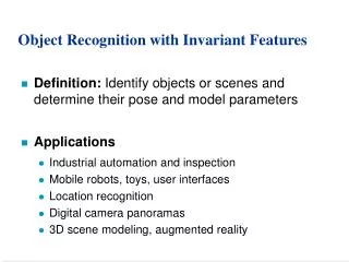
Introduction • Object Recognition • Recognize known objects in unknown configurations
Previous Work • Zhang et al • Harris Corner Detection • Detect peaks in local image variation • Schmid and Mohr • Harris Corner Detection • Local image descriptor at each interest pt from an orientation-invariant vector of derivative-of-Gaussian image measurements
Motivation • Limitations of previous work: • Examine image only on a single scale • Current paper addresses this concern by identifying stable key locations in scale space • Identify features that are invariant
Invariance • Illumination • Scale • Rotation • Affine
Scale Space • Different scales are appropriate for describing different objects in the image, and we may not know the correct scale/size ahead of time.
Difference of Gaussian • A = Convolve image with vertical and horizontal 1D Gaussians, σ=sqrt(2) • B = Convolve A with vertical and horizontal 1D Gaussians, σ=sqrt(2) • DOG (Difference of Gaussian) = A – B • Downsample B with bilinear interpolation with pixel spacing of 1.5 (linear combination of 4 adjacent pixels)
B1 A1 Difference of Gaussian Pyramid A3-B3 Blur B3 DOG3 A3 Downsample A2-B2 B2 Blur DOG2 A2 Input Image Downsample A1-B1 Blur DOG1 Blur
Pyramid Example A3 DOG3 B3 A2 B2 DOG3 A1 B1 DOG1
Feature detection • Find maxima and minima of scale space • For each point on a DOG level: • Compare to 8 neighbors at same level • If max/min, identify corresponding point at pyramid level below • Determine if the corresponding point is max/min of its 8 neighbors • If so, repeat at pyramid level above • Repeat for each DOG level • Those that remain are key points
Identifying Max/Min DOG L+1 DOG L DOG L-1
Refining Key List: Illumination • For all levels, use the “A” smoothed image to compute • Gradient Magnitude • Threshold gradient magnitudes: • Remove all key points with MIJ less than 0.1 times the max gradient value • Motivation: Low contrast is generally less reliable than high for feature points
Assigning Canonical Orientation • For each remaining key point: • Choose surrounding N x N window at DOG level it was detected DOG image
Assigning Canonical Orientation • For all levels, use the “A” smoothed image to compute • Gradient Orientation + Gradient Orientation Gradient Magnitude Gaussian Smoothed Image
Assigning Canonical Orientation • Gradient magnitude weighted by 2D gaussian = * Gradient Magnitude 2D Gaussian Weighted Magnitude
Assigning Canonical Orientation • Accumulate in histogram based on orientation • Histogram has 36 bins with 10° increments Weighted Magnitude Sum of Weighted Magnitudes Gradient Orientation Gradient Orientation
Assigning Canonical Orientation • Identify peak and assign orientation and sum of magnitude to key point * Peak Weighted Magnitude Sum of Weighted Magnitudes Gradient Orientation Gradient Orientation
Refining Key List: Rotation • The user may choose a threshold to exclude key points based on their assigned sum of magnitudes.
Example of Refinement Filter for illumination Max/mins from DOG pyramid Filter for edge orientation
Local Image Description • SIFT keys each assigned: • Location • Scale (analogous to level it was detected) • Orientation (assigned in previous canonical orientation steps) • Now: Describe local image region invariant to the above transformations
Local Image Description For each key point: • Identify 8x8 neighborhood (from DOG level it was detected) • Align orientation to x-axis
Local Image Description • Calculate gradient magnitude and orientation map • Weight by Gaussian
Local Image Description • Calculate histogram of each 4x4 region. 8 bins for gradient orientation. Tally weighted gradient magnitude.
Local Image Description • This histogram array is the image descriptor. (Example here is vector, length 8*4=32. Best suggestion: 128 vector for 16x16 neighborhood)
Database Creation • Index all key points of reference model image(s) • Store key point descriptor vectors in database
Image Matching • Find all key points identified in target image • Each key point will have 2d location, scale and orientation, as well as invariant descriptor vector • For each key point, find similar descriptor vectors in reference image database. • Descriptor vector may match more than one reference image database • The key point “votes” for image(s) • Use best-bin-first algorithm
Hough Transform Clustering • Create 4D Hough Transform (HT) Space for each reference image • Orientation bin = 30° bin • Scale bin = 2 • X location bin = 0.25*ref image width • Y location bin = 0.25*ref image height • If key point “votes” for reference image, tally its vote in 4D HT Space. • This gives estimate of location and pose • Keep list of which key points vote for a bin
Verification • Identify bins with largest votes (must have at least 3). • Using list of key points which voted for a cell, compute affine transformation parameters (m, t) • Use corresponding coordinates of reference model (x,y) and target image (u,v).
Verification • If more than three points, solve in least-squares sense
Verification: Remove Outliers • After applying affine transformation to key points, determine difference between calculated location and actual target image location • Throw out if: • Orientation different by 15° • Scale off by sqrt(2) • X,Y location by 0.2*model size • Repeat least-squares solution until no points are thrown out
Advantages of SIFT • Numerous keys can be generated for even small objects • Partial occlusion/image clutter ok because dozens of SIFT keys may be associated with an object, but only need to find 3 • Object models can undergo limited affine projection. • Planar shapes can be recognized at 60 degree rotation away from camera. • Individual features can be matched to a large database of objects
Limitations of SIFT • Fully affine tranformations require additional steps • Many parameters “engineered” for specific application. May need to be evaluated on case-to-case basis